Maker Pro
Maker Pro

Scorched Component Can't Indentify

csf2020

Jun 19, 2019
5
Joined
Jun 19, 2019
Messages
5
I have what I think is a resistor on a small board from the turn table in a Victrola 6in1 player. I peeled off glue type stuff that probably help keep things stable. There was evidence of heat on this glue stuff. In the pictures you can see it next to the capacitor. The color and stripes are gone from getting hot I think.The motor runs on 12 volts DC and is a servo motor. The motor changes speeds depending on the record size speed selection. I would like to try replacing this component, but I can't identify it. I can't find a schematic for the player either.

I have 2 pictures, but I'm getting an upload error from the website. They are just under 2 mb each. Okay I had to make them smaller.
 
Last edited:

Bluejets

Oct 5, 2014
6,922
Joined
Oct 5, 2014
Messages
6,922
There are plenty of online sites that will resize your images if you do not have any installed on your pc.
 

csf2020

Jun 19, 2019
5
Joined
Jun 19, 2019
Messages
5
I re sized and thought I successfully uploaded last night, but nothing here. I'll try again.
 

Attachments

  • IMG_0182.jpg
    IMG_0182.jpg
    243.9 KB · Views: 21

Bluejets

Oct 5, 2014
6,922
Joined
Oct 5, 2014
Messages
6,922
There may well be other problems that made the resistor cook itself in that way.
However it is sometimes possible to still get a reading from a burnt resistor.

Looks like the white socket on the board (CN1) might plug in to what appears as a matching white plug on the motor.
Then again the motor white plug seems to have 9 pins so perhaps a speed control encoder as well as power.
In which case there should be more to the circuit than what we can currently see.

WE are kind of flying blind here so any extra info from you is bound to help in some way.
Can you get another photo of the rear of the board also and anything else you may have "unplugged".

Well done on this pic though, exactly what is required.
 

csf2020

Jun 19, 2019
5
Joined
Jun 19, 2019
Messages
5
The open plug goes to the system for power and sound output. I may have an issue with the incoming voltage. I saw 17 volts yesterday and now today zero. I'll try to gather some more information.
 

73's de Edd

Aug 21, 2015
3,622
Joined
Aug 21, 2015
Messages
3,622
Sir csf2020 . . . . .

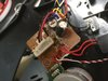
Mah fren' . . . . . .what you has yerselfs there . . . is a scorched carbon film resistor.
Initially just place an ohmmeter across its two leads to see what you possibly might read between its two leads . . . hoping that switches associated with it might be keeping any resistive shunting of it by another component(s). Ergo an impossible verification of its TRUE ohmmic value.
To burn like it has . . . . it must be at or below a 10 ohms value . . .considering that specified 9-12 VDC spec on the motor /supply.

Correct me if wrong . . . but dont you start the turntable by lifting the tone arm from its rest and the motor starts then you place the arm on the start of fthe record lead in grooves. . . it plays thru . . .and then the end of the record is detected by the small microswitch (marked with 1A 125V AC) with its 2 black leads being mechanically activated by a lever.
What looks to be a LARGER switch is the BLACK unit with RED wwires and PCB identified as SW2 and is being vewy-vewy-VEWY close to your fried resistor.

If you never got a low ohmmic reading on the existant resistor and you got an open reading or HIGH one , you need access to the foil side of that circuit board.

See if that 17VDC which you mention is connected to either side of that burnt resistor, there might be a regulated supply that feeds the motor and it has lost regulation and is feeding excess voltage to the motor supply.

If receiving 12 V that overloading of the resistor would seem likely of a motor problem, and they usually incorporate a power ttransistor in their speed control circuitry.
Confirm that your unit has one on the back of the terminal board of he motor and use these references of the motor, of which one of the sites has 7 different motor shots and the transistor can be seen on one of those photos.

https://picclick.com/Record-Player-Turntable-Drone-Parts-Electric-Motor-Engine-143166171698.html

https://www.ebay.com/itm/143166171698

Come back with your feedback and then we see which direction we need to go.

73's de Edd

Some of it . . . plus the rest of it . . . is all of it.
 
Last edited:

csf2020

Jun 19, 2019
5
Joined
Jun 19, 2019
Messages
5
You are correct about the operation with the exception that the only power feeding the turn table assembly come from the 17 volt power source in the plug. I may have screwed up by putting in a used 5 ohm resistor and trying it out. The size and primary color looked the same. BTW the burnt resistor did not read any ohms at all. To continue I seem to have lost my 17 volt feed which my be from my putting in the used resistor. I won't lie I'm in over my head. :) Thanks for the great information de Edd.
 

73's de Edd

Aug 21, 2015
3,622
Joined
Aug 21, 2015
Messages
3,622
Sir csf2020 . . . . . .

OK on your other info.
Now since you can, and have "sartered ". . . . . .on that pulled original resistor.

I usually place the ohmmeter in its lowest range that would accomodate the suspected resistance value. Then I grip one meter probe against the top alum tab of a single edge razor blade and touch the other probe with the sharp edge to confirm a continuity . The free probe gets connected to the suspected good resistor lead at the "good" end. Or, you can use a clip lead to join both resistor ends together.
Then I move to the resistor and place the sharp blade adge against the center area to receive multiple, light scrapes with the blade. Set it a wee bit off vertical and lightly scrape until an ohms reading appears. Pull the jumper clip and reconfirm your reading.
In the rare chance that no reading is possible, work with only a 1/3 or 1/4 of the length of the resistor from its end.

OK on the power aspect . . . I believe that the AC power cord enters the unit and thereby, has no external power block or wall wart for its 30 w power need . . . . right ?
Do any or all of the other functions still operate, or have you also lost power to them ?

RELEVANT REFERENCING INFO . . . . .

upload_2019-6-21_4-37-50.png

73's de Edd . . . . .

FACTOID . . .
The statistics on sanity is that one out of every four persons is suffering from some sort of mental illness.
Then think of your three best friends — if they’re all okay, alas, then it’s YOU.


csf2020

Jun 19, 2019
5
Joined
Jun 19, 2019
Messages
5
Everything works except the turn table. Yes the power in is a cord with no external transformer. I tried the above method of identifying the resistor and had no readings at all. Perhaps I took off to much material and completely broke the connection.
 

73's de Edd

Aug 21, 2015
3,622
Joined
Aug 21, 2015
Messages
3,622
How about 2 close in, straight on from top, photos of the two sides of the PCB to see how connections are made.
 
Top