Maker Pro
Maker Pro

RF Choke Repair

Kilo Echo

Oct 16, 2016
5
Joined
Oct 16, 2016
Messages
5
Greetings.
The attached image shows a 4-section RF choke the wire broken flush with the component. I'm not going to attempt to solder the wire at the break point.
I'm not familiar with these chokes and would like to know if it can be repaired by soldering the broken wire to the stub adjacent to the original connection.
Thanks
 

Attachments

  • IMG.JPG
    IMG.JPG
    159.1 KB · Views: 91

duke37

Jan 9, 2011
5,364
Joined
Jan 9, 2011
Messages
5,364
Looks as if you can repair by soldering the wire to the stub. If necessary you could take off one turn.

If it is Litz wire (lots of very fine strands) then it will be difficult to get them all to wet. A solder pot can be used with copious amounts of flux.
 

73's de Edd

Aug 21, 2015
3,628
Joined
Aug 21, 2015
Messages
3,628
Kilo Echo . . . . . . . Victor Yankee . . .here . . . .

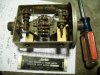
You can see that the left end of that tri- wound choke goes to a ground lug and the right ends "stub" just appears to have experienced a metal fatigue break.

Ohm from the chokes very left terminal to the wire "stub" to see if you have continuity of the series winding

If so, then scrape the wires clean of oxide and tin both the long wire length and the short stub, and then do a wrap around of the long wire to the stub and do a final solder reflow.

If the wire from the smallest coil layer over to the stub is broken, I just get its end sticking up in the air and use copious amounts of rosin flux and solder on the tip of my WELL TINNED iron until I finally get a tinned blob.

Then an additional solid wire is tinned and wound around the "stub" and reflow soldered down.
Now, the other end of the wire is fashioned into a very small teardrop loop and tinned.
Then the tinned Litz wire end is inserted into the teardrop and reflow soldered.
With all continuity tests then passed, possibly add a drop of service cement to additionally mechanically anchor the repair area to the coil form.

What is the brand and model of this old piece of equipment, with what looks like a non inductive type of quasi dummy load up above ?
With the resistor cluster having its bottom end terminating to an old SO-239 RF connector, and this choke is then RF isolating, but DC grounding it .


73's de Edd
 
Last edited by a moderator:

Kilo Echo

Oct 16, 2016
5
Joined
Oct 16, 2016
Messages
5
Thanks for the replies, duke37 and 73's de Edd.
The break wasn't at the stub, but just beneath it, flush with the end of the choke.
There is continuity between the right stub and the left terminal (ground). The unit uses 3 of these chokes, all have continuity between the long wires and stubs. I'm beginning to think that the stubs (is there a more technical term for these?) are there for the very purpose of repair.
The unit is a Micro-Match coupler, model 261.1, manufactured by M.C. Jones. It is part of a power/VSWR meter.
 

Attachments

  • IMG1.JPG
    IMG1.JPG
    168.7 KB · Views: 61

73's de Edd

Aug 21, 2015
3,628
Joined
Aug 21, 2015
Messages
3,628
Kilo Echo . . . . . . . Victor Yankee . . .here . . . .

I now see your concern . . .so I am bestowing X-ray vision upon you, for enhanced comprehension.

I moved to a better choke view sample and its end.
Those coil forms have the wire terminals on each end, imbedded within the molding as is
being shown within the YELLOW . . .otherwise obscured . . .wire loops internals.
They will use the long wire length for connecting to circuits, while using the short stub to bring the coils Litz wire up to and coil around it and then reflow solder.

VISUAL:

COIL FORM TERMINUS.jpg

Thasssssit . . . . . .


73's de Edd
 
Last edited by a moderator:

Kilo Echo

Oct 16, 2016
5
Joined
Oct 16, 2016
Messages
5
Aha! Now that makes sense.
That x-ray vision must come in handy!
Thank you, sir, for your time. I appreciate it.
73s
 
Top