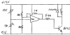
Ive built this circuit  to keep wine at a constant temperature while fermenting. The problem Ive got is the relay, which is switching 240v chatters when turning off. There`s a nice clean click when turning on. Can anyone suggest how to correct this?
to keep wine at a constant temperature while fermenting. The problem Ive got is the relay, which is switching 240v chatters when turning off. There`s a nice clean click when turning on. Can anyone suggest how to correct this?