Hi,
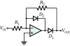
I'm using the ADC on an ATtiny24 to record a AC signal. The ADC has a range from 0-3.3V. I'm using a precision rectifier to get rid of the negative portion of the signal. I've attached a picture of the circuit I'm using for the rectifier. I'm using an LMC6484 as the op-amp with 3.3V to the V+ rail and 0 to the V- rail. I'm using 1N4004's as the diodes and 10k for the resistors.
Image.jpg shows a signal on an oscope after being sent through the data logger. Rect.jpg shows how my logger interprets the signal. It follows the function generator pretty well. BUT the oscope shows that the signal varies from -0.5 to 1V. But my micro shows a signal with the same waveform that goes from 0-1.5V! If I replace the precision rectifier with a simple diode/resistor combination, I get a waveform that varies from -0.X volts to Y volts (depending on the input through the function generator). The micro logs the waveform correctly but the voltage range is from 0.X to Y volts.
I always have a little bit of a negative signal even with the precision rectifier and when I graph the results through my logger, it appears that the largest negative value has been moved up to zero, so I seem to get a larger range than the input.
Is this a result of putting in negative voltages into my ADC? Does it take the negative voltages, set that as 'ground' with respect to other voltages?
I've input positive voltages into the logger through a power supply, and it reads those voltages perfectly!
All my grounds are connected together, so I know that isn't a problem. Honestly, I'm at my wit's end!