Maker Pro
Maker Pro

PSU 5V line seemingly not performing

foggy

May 9, 2021
7
Joined
May 9, 2021
Messages
7
Hi!

Quite new to this so please forgive me if I'm not wording things correctly etc!

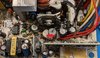
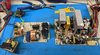
I have a computer power supply. It's not ATX but reasonably similar I think. It's from a small IBM AS/400 model 150 computer. The PSU model is IBM Part# 40H7561 made be Delta Electronics and carries a Delta Part# DPS-250CB A. If I google the DPS part number I get images that don't really look like this PSU!

I have two of these computers. One works perfectly, the other does not. I've changed components around between the two computers and the problem definitely follows the PSU.

There's a small LCD display panel and associated circuitry that should come on as soon as mains electricity is provided. I'm pretty sure this is powered by the +5V line on the PSU. Once that powers up, it is then possible to switch on the computer properly.

The problem is that the panel isn't properly powering up. The LCD is faint and none of the panel buttons do anything. Sometimes, I can cajole the computer into switching on. When it does, it all works fine except for the front panel. It remains dark. So this is my thinking as to how I've isolated the problem to the 5V line.

I do however see 5V on the aux line on the PSU. If I short the Power on to GND, the PSU fires up properly and I see correct voltages on the other lines (12V, 5V, -5V etc).

There's two capacitors near where the 5V line connects. I've removed and tested them and they show good uF readings as far as I can tell.

As I say, if I switch the PSU out for another one, it all works just fine.

Is it possible that the 5V line isn't providing enough power? What can I do to check and fix this?

cheers!
fog
 

Martaine2005

May 12, 2015
4,949
Joined
May 12, 2015
Messages
4,949
I would check the capacitors for high ESR not capacitance. Replace them, they are too cheap to worry about.
Then check the PSU again.

Martin
 

dave9

Mar 5, 2017
1,188
Joined
Mar 5, 2017
Messages
1,188
I don't understand your issue. Put the caps back in. Measure the 5V rail in question. Is it reading near 5.0V while connected and powering the system?

Filter caps for this type of SMPS tend to be fine until they vent, particularly when not near peak load. There are exceptions but it seems to make more sense starting with more likely things rather than less likely.

However having multiples of this PSU, and two known (otherwise) working systems, it would be much easier to probe and compare readings between the two, but you must be safety conscious when working on something exposed to live mains and higher voltage, including some *surprises* like the primary side heatsink may be at a few hundred volts.

If you don't feel comfortable with live testing, you could still pull the PCB and examine the bottom for bad solder joints, though I assume you must have already pulled it, to get the caps out to test.
 

foggy

May 9, 2021
7
Joined
May 9, 2021
Messages
7
Hi
Dave - The whole thing is back and assembled. Yes, I get 5V on the aux and, as I say, if I connect the power on to ground, the 'rest of' the PSU fires up just fine. I've compared voltages on each of the pins on the known good and sick PSU and they appear to be the same. With the PSU in 'standby' ie with it in a state that only the 5V aux line us supplying power, it doesn't even power up the front panel properly. It's like it can't supply enough juice to the panel even though it reads 5V. This is where my understanding stops and is why i ask here!

I understand the need to be careful, I carefully drain the big 250V caps on the primary side and check voltage before going near it with my fingers, but thanks for the concern.

Martin, I'll investigate this ESR and will likely look to replace the caps. Are you suggesting to replace the caps near that 5V line or all of them? As I say, I can sometimes make it fire up and boot the server fine so that sort of tells me the rest of the PSU is fine. A bunch of the other caps are glued in with some white crap that'll make the whole enterprise challenging...

Cheers guys
fog
 

Martaine2005

May 12, 2015
4,949
Joined
May 12, 2015
Messages
4,949
By your diagnosis, it sounds like the 5V rail is present until under load.
A simple test would be to tack another capacitor across the existing one.
But as @dave9 says, you have two to compare measurements.

Martin
 

dave9

Mar 5, 2017
1,188
Joined
Mar 5, 2017
Messages
1,188
I would test the diode just before the 5V caps.
 

foggy

May 9, 2021
7
Joined
May 9, 2021
Messages
7
Suspect PSU: with no load on the aux 5V, it reads 5V. With the connector plugged into the motherboard, it drops to 3.3V
Known good PSU: 5V with no load, also 5V with load.
 

foggy

May 9, 2021
7
Joined
May 9, 2021
Messages
7
Which is the diode you refer to? Pic uploaded. The 5V aux lines are the red ones pointed by the arrow.
The caps just above are the ones I tested.
 

Attachments

  • closeup.jpg
    closeup.jpg
    324 KB · Views: 8

dave9

Mar 5, 2017
1,188
Joined
Mar 5, 2017
Messages
1,188
Use the bottom of the PCB to trace the circuit away from the caps towards the input. Test everything in that path, and compare voltage readings to the other PSU, both when under load, connected to the system.
 

foggy

May 9, 2021
7
Joined
May 9, 2021
Messages
7
hmm was hoping not to have to crack open the working one.... but I guess it makes sense if I have a reference one right there.
 

foggy

May 9, 2021
7
Joined
May 9, 2021
Messages
7
Well... isolated the problem to the 470μF capacitor to the lower right of that smaller transformer.

I removed them both and they each measured around 470μF however the one from the broken PSU was reading about 5MΩ when I measured the resistance while the known good was up around 8MΩ.

Switched them around and previously duff PSU came right up!

thanks for the pointers.... happy I know more about these things now! One question though, if I didn't have the other PSU to reference, how would I know that capacitor was duff?

cheers,
fog
 

dave9

Mar 5, 2017
1,188
Joined
Mar 5, 2017
Messages
1,188
Heh, well... I was about to suggest that you should be opening the other PSU anyway to clean them both out, because the one that is pictured, either the cap to the lower right of the small transformer is filthy or it has vented electrolyte, normally there wouldn't just be one capacitor that managed to build up gunk like that.

THEN, I was about to suggest that if the computers are important, it would be a good idea to replace most of the capacitors in these, since it's probably an over 20 years old PSU. And the fans.

The questionable cap could have its ESR measured, but keep in mind that this cap (and others) may be about to fail in the other still working PSU, given same PSU model, age, possibly same use environment? Better not to have them fail then see if the powered equipment suffers any damage.
 

Martaine2005

May 12, 2015
4,949
Joined
May 12, 2015
Messages
4,949
if I didn't have the other PSU to reference, how would I know that capacitor was duff?
Sometimes, a visual inspection can be all that's needed. By either a swollen top, vented top, obvious leakage or out right blown a part.
But an ESR meter is by far the best way.
If the cap/s are not shorted, a similar cap tacked to the suspect one usually improves performance immediately. Therefore proving that cap is faulty or failing.
As @dave9 said, I too would have replaced all electrolytics as a matter of course.

Martin
 

foggy

May 9, 2021
7
Joined
May 9, 2021
Messages
7
Yeah, both PSU's were filthly inside. The computers were too. I think they must have come from a dirt factory or something.

Regarding that capacitor - once I extracted it, it was obvious that something had leaked, it was a bit sticky and that, I guess had attracted more dirt to stick to it.

So I've identified all the caps below the line. The ones to the right above the line are covered in some goop that I'll need to pick off. The computers are quite important since they don't come on ebay all that often these days so I'd like to expend the effort doing it right.
 

Attachments

  • Screenshot 2021-05-11 095000.jpg
    Screenshot 2021-05-11 095000.jpg
    288.5 KB · Views: 3

dave9

Mar 5, 2017
1,188
Joined
Mar 5, 2017
Messages
1,188
Yeah it might be easier to use desoldering wick or a solder sucker to get the solder off then remove them as a group, though I suppose it doesn't matter much if you damage the casing picking the cement/whatever-goop off if you plan to replace them.

The other option if you can identify the function of all wires, is take the wiring harness off these PSU and make an adapter with ATX motherboard connectors so you can use a standard ATX PSU... at least it "seems" like maybe this has 5VSB and soft-on rather than a mechanical switch to turn AC mains on, right? That was my impression, that it might be near or actual ATX electrically but with AT mainboard connectors, not necessarily using the AT pinout.
 
Top