Maker Pro
Maker Pro

Project question

SparkyCal

Mar 11, 2020
849
Joined
Mar 11, 2020
Messages
849
I have a little ornament on my guitar that I would likem to light up with 6 LEDS. I'd like for them to automatically liight, when it is dark.

I have photo resistors with the specs listed below, but I am understanding that they would have the opposite effect- ie: turn the lights on when it is not dark. How could I make them go on when it is dark?

Thnak-you


5mm GM5539 Photoresistor:
Maximum voltage: 150 Volt DC
Spectral peak: 540 nm
Maximum wattage: 100 mW
Light resistance (10 Lux): 50-100 Kohm
Operating temperature: - 30 ~ + 70 degree Celsius;
 

Bluejets

Oct 5, 2014
6,926
Joined
Oct 5, 2014
Messages
6,926
It will do either depending how it is set up.
Normal approach is to connect in a voltage divider arrangement and if the LDR is in the top leg, effect is opposite to that when it is in the bottom leg.
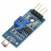
There are small modules on Ebay etc. which have a comparator so you can select the switching point or sensitivity if you like.

I am certain we gave you the address of "talkingelectronics" website which should have a circuit and explanation.
Go take a look there first.
 

Nanren888

Nov 8, 2015
622
Joined
Nov 8, 2015
Messages
622
These two appear in the datasheet for the part from WDYJ GM5539.
upload_2020-5-15_16-26-15.png
There are small modules on Ebay etc. which have a comparator so you can select the switching point or sensitivity if you like.
A ready-made module will offer you more options/control.

.
 

SparkyCal

Mar 11, 2020
849
Joined
Mar 11, 2020
Messages
849
Thank you for all the advice. I also found the circuit below on an electronics app that I purchased. Wonder if the one on the right would work
upload_2020-5-15_17-31-13.png
[mod edit: rotated the image]


I wonder why the diagram does not specify the voltage to apply
 
Last edited by a moderator:

SparkyCal

Mar 11, 2020
849
Joined
Mar 11, 2020
Messages
849
Thank you for all the advice. I also found the circuit below on an electronics app that I purchased. Wonder if the one on the right would work View attachment 48224


I wonder why the diagram does not specify the voltage to apply
Sorry about the diagram being sideways. It was the right way beforehand
 

Harald Kapp

Moderator
Moderator
Nov 17, 2011
13,723
Joined
Nov 17, 2011
Messages
13,723
I wonder why the diagram does not specify the voltage to apply
This is a simple circuit and not very accurate. It will work probably in the range 4.5 V ... 9 V.
Note that the emitter resistor is labeled R only. It is up to you to calculate the required value depending on supply voltage, LED current and number of LEDs in series (I assume you have a few). See our resource on driving LEDs for more details.
With a few LED in series the required supply voltage increases to Vsupply > n × Vled.
Example: White LEDs have a forward voltage of ~3 V. 6 (the number you gave) LEDs in series require more than 18 V supply voltage. You may be better off creating 2 parallel strings of 3 LEDs in series. See my post #5 in this thread for how it is done. You may get away with a 9 V battery in this setup.
Ignore the MOSFET but observe the placement of the current limiting resistor: each string needs its own resistor. Therefore connect the emitter of the HNP transistor from your schematic directly to battery "-" and connect the LED strings with their separate resistors to the collector of the NPN transistor.

This is possibly the simplest circuit that is nevertheless good enough for the humble service you ask of it. Give it a try.
 

SparkyCal

Mar 11, 2020
849
Joined
Mar 11, 2020
Messages
849
Thank-you for the replies. I plan to loop back to this and read it carefully when I finish a current project, and mover on to this one. Thank-you.
 
Top