Maker Pro
Maker Pro

Problems building first circuit - capacitor ESR meter

Jaynuts

Mar 11, 2012
13
Joined
Mar 11, 2012
Messages
13
Hello

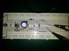
This is my first real circuit built only from schematics. It is for my physics A2 coursework. The circuit operates on monostable 555 IC and is powered by a 9V battery. It is SUPPOSED to display and ESR of a capacitor that i connect to the terminals, on the analogue display. Unfortunately i get no result on the display. I have built 2 circuits: 1 at home and one in classroom - both seem to have a normal current flow through whole circuit (no short circuit) but i get no indication of ESR. I'd be grateful for any help regarding my non-working circuit. I will link an original website as well as pictures of my circuit from classroom. As i said this is my first time so be gentle :)

(also i do realise that the rightmost resistor is in wrong hole i did change that and still no luck).

Thanks, any help would be appreciated.

Original Schematics Website (it's in czech but really the schematics matters),
 

Attachments

  • case1.jpg
    case1.jpg
    148.5 KB · Views: 5,892
  • case2.jpg
    case2.jpg
    154 KB · Views: 4,774
Last edited:

jackorocko

Apr 4, 2010
1,284
Joined
Apr 4, 2010
Messages
1,284
Ok, well if you want help you will need to fix the link to the schematic and also link to the real photos and not the thumbnails.

As a start I would connect pin4 to Vcc, so you can at least eliminate that issue.
 
Last edited:

Jaynuts

Mar 11, 2012
13
Joined
Mar 11, 2012
Messages
13
Pin 4 is the 555's reset and it is active low.

I'm sorry to be a pain: what is "active low"? And why do i need to connect to reset if i use 555 as monostable? (sorry i'm new to this.) Also how can i check the resistance with my multimeter? The analogue meter is at school i only have a digital multimeter with me and when i set to ohms it shows same value when there is a capacitor at Cx and when there is a wire at Cx.

Thanks
 

Attachments

  • case3.jpg
    case3.jpg
    125.2 KB · Views: 1,560
  • case4.jpg
    case4.jpg
    144.4 KB · Views: 1,846

jackorocko

Apr 4, 2010
1,284
Joined
Apr 4, 2010
Messages
1,284
The measuring principle is simple: The capacitor is connected alternating current with high frequency (typically 50-100kHz) and measure the voltage drop on it

From the description on the website of how it works I would say you want the 555 to run in astable mode.

active low means that when the signal on pin 4 is low the reset function is active. This keeps the 555 from working.

Anyway, someone else will have to help you out further. The way that 555 is hooked in the link you provided is unconventional to me.
 

(*steve*)

¡sǝpodᴉʇuɐ ǝɥʇ ɹɐǝɥd
Moderator
Jan 21, 2010
25,510
Joined
Jan 21, 2010
Messages
25,510
The way that 555 is hooked in the link you provided is unconventional to me.

That is a configuration which gives an output of as close to 50% duty cycle as you're going to get with a 555.

It uses the output to provide the current source/sink path, ensuring that the charge/discharge is via the same resistor.

Assuming the output is not unevenly loaded and that the output of the 555 is pretty symmetrical, the RC constant for charging and discharging are equal.
 

Jaynuts

Mar 11, 2012
13
Joined
Mar 11, 2012
Messages
13
...Assuming the output is not unevenly loaded and that the output of the 555 is pretty symmetrical, the RC constant for charging and discharging are equal.

Therefore would i get some reading on a analogue display if i connect the 4 to 8 at school?
 

(*steve*)

¡sǝpodᴉʇuɐ ǝɥʇ ɹɐǝɥd
Moderator
Jan 21, 2010
25,510
Joined
Jan 21, 2010
Messages
25,510
you will almost universally find that pin 4 is tied to pin 8 in astable oscillators using a 555. I'd go with that :)

edit: your first test is to ensure the 555 is oscillating. Measure the voltage on pin 3. It should probably measure about 1/2 the supply voltage. If it measures zero or the full supply voltage then it's not oscillating.
 

Jaynuts

Mar 11, 2012
13
Joined
Mar 11, 2012
Messages
13
you will almost universally find that pin 4 is tied to pin 8 in astable oscillators using a 555. I'd go with that :)

great, thanks. I really do hope it will work i spent last week (4 lessons) building and debugging this circuit. Now i only have another week left hopefully this will do :)

Thanks
 

(*steve*)

¡sǝpodᴉʇuɐ ǝɥʇ ɹɐǝɥd
Moderator
Jan 21, 2010
25,510
Joined
Jan 21, 2010
Messages
25,510
Your layout on the breadboard is also a little unusual.

You normally don't snake the power supply the way you have. It's normally via links to the upper and lower row of holes. Also it's bad form to put 2 wires in the same hole.

(Also note my edit in my previous message)
 

Jaynuts

Mar 11, 2012
13
Joined
Mar 11, 2012
Messages
13
Your layout on the breadboard is also a little unusual.

You normally don't snake the power supply the way you have. It's normally via links to the upper and lower row of holes. Also it's bad form to put 2 wires in the same hole.

(Also note my edit in my previous message)

I bridged the indicator connections and attached black multimeter lead to - and red to pin 3. i get a reading of around -65mV and still growing. What is wrong with this circuit?
 

Attachments

  • case5.jpg
    case5.jpg
    117.7 KB · Views: 885
Last edited:

Jaynuts

Mar 11, 2012
13
Joined
Mar 11, 2012
Messages
13
ok i've added the image of how i connected it as well.

thanks for any help.
 

(*steve*)

¡sǝpodᴉʇuɐ ǝɥʇ ɹɐǝɥd
Moderator
Jan 21, 2010
25,510
Joined
Jan 21, 2010
Messages
25,510
It sounds like it's not oscillating then.

You need to work on the oscillator. Do stuff like checking to make sure the +ve rail and ground rail are present (you may have a bad connection on the breadboard). It's also possible the 555 may be damaged.

It's also possible that your multimeter doesn't work well at 48kHz or so.

Perhaps you can use an oscilloscope to check that out.
 

Jaynuts

Mar 11, 2012
13
Joined
Mar 11, 2012
Messages
13
It sounds like it's not oscillating then.

You need to work on the oscillator. Do stuff like checking to make sure the +ve rail and ground rail are present (you may have a bad connection on the breadboard). It's also possible the 555 may be damaged.

It's also possible that your multimeter doesn't work well at 48kHz or so.

Perhaps you can use an oscilloscope to check that out.

i do have a personal scope but i don't know how to use it :p

Thanks for the suggestions though i will keep trying.
 

(*steve*)

¡sǝpodᴉʇuɐ ǝɥʇ ɹɐǝɥd
Moderator
Jan 21, 2010
25,510
Joined
Jan 21, 2010
Messages
25,510
I would lay my bets on your 555 not oscillating.

If you can get another one and make the same circuit (but just the 555 part) and use a capacitor about 100 times larger (say 68nF -- 0.1uF is something you may have on hand) then see if you can hear it oscillate (connect a speaker via a capacitor -- 10uF -- and a resistor -- 100R -- and you should be able to hear it. Once you know it is oscillating, read the voltage at the output and you should see 1/2 your supply voltage. Then change the capacitor back to the original 680pF and the voltage on the output should remain roughly the same. Then add the rest of the circuit.
 

Jaynuts

Mar 11, 2012
13
Joined
Mar 11, 2012
Messages
13
@jaynuts
What kind of diode you use in D1 and D2?

These are both rectifier diodes. Not as quick as Schottkys but they work.

I just came back from the lesson and it turns out my 820R was in the wrong place. The circuit now works. I think i didnt get a multimeter reading because the 555 worked in a monostable setting and so there were no pulses. This circuit works on ~10uF electrolytic polarised capacitors. I may also modify R1 and R2 values in the RC network to modify accuracy but everything is fine now. Thanks for all the help guys!
 

jackorocko

Apr 4, 2010
1,284
Joined
Apr 4, 2010
Messages
1,284
I think i didnt get a multimeter reading because the 555 worked in a monostable setting and so there were no pulses.

This doesn't really make any sense, the 820Ohm resistor should have nothing to do with the function of the 555 in this circuit. The 555 has and will always be in this circuit running in astable mode.
 
Top