Maker Pro
Maker Pro

power board - don't know what to try

sparkmonkey

Feb 24, 2014
13
Joined
Feb 24, 2014
Messages
13
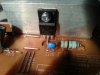
This is the power board from a samsung monitor/tv. The thing stopped working completely with a bit of a bang, so I figured no harm to have a go as an enthusiastic newbie. I got a bit stuck now, so I thought I'd ask for advice here before I throw the whole thing in the bin.

On opening the case it was clear that the resistor at A had blown, you can see the residue on the board, so I replaced that. The capacitor at C was slightly bowed outwards at the top, so I replaced that. All the other capacitors look fine. On putting the thing back together and switching on fuse B blows. I have tried replacing also capacitors at D, and the fuse at B blows still.

What should I try now? My assumptions are that it is most likely to be a fault on this board - is that a reasonable working assumption or could something broken in another part of the monitor entirely cause these sort of symptoms?

Is it reasonably safe to test this board in isolation by connecting it to the power and trying a voltmeter on the output cables in the bottom right corner which seem to be marked +15v and ground. What other diagnostic checks are worth doing?
 

Attachments

  • WP_20140326_013.jpg
    WP_20140326_013.jpg
    147.5 KB · Views: 410

sparkmonkey

Feb 24, 2014
13
Joined
Feb 24, 2014
Messages
13
ahh when I said 'not working' - the whole monitor was dead, no signs of life at all. Thought it would be helpful to clarify that.
 

(*steve*)

¡sǝpodᴉʇuɐ ǝɥʇ ɹɐǝɥd
Moderator
Jan 21, 2010
25,510
Joined
Jan 21, 2010
Messages
25,510
These are generic instructions. You have done part of this already.

First things first. There are high voltages there, and whatever happens I don't want to hear that you let out a little noise and now you've stopped working...

High voltages = can kill you -- OK?

You see the power connector. The board has a thick white line . Everything inside that outlined area is "live" when the power is connected, and high voltages can remain after the power is disconnected (up to 400V).

So don't go sticking your fingers in there even after the power has been removed. Even if it doesn't kill you, it may make you wish you were for a few seconds (it can really hurt -- ask me how I know).

Do you have a multimeter (If you don't, you can't do much)

The first thing to do is to leave it for at least an hour after it was last switched on and remove the fuse. Check the fuse with the meter. It should measure close to 0 ohms (not OL). Reading OL means it's died. [There are 2 fuses, only the second one blows -- what are the ratings of both fuses?]

If it's failed, it will possibly fail again as soon as you replace it. You could try, but if you do, have at least a couple of spares and only try it ONCE. [You've done that]

Assuming that you either decide not to try it, or it blew the fuse, the next think to look at is the three terminal device attached to the heatsink near the lower left corner of the image. Does it have any chunks blown out of it? Is there ant smokey residue near it, does it appear cracked? Burn marks? If you can, tell us exactly what is written on the body of this. [Do this]

There is a bridge rectifier -- the black thing to the left of Fuse B. Cracks, chunks, burn marks(?) as above, and get the details written on it. [do this]

Read the voltage across the large filter capacitor (450V 150uF). This one can bite, OK! Do it with 1 hand if you can. If the voltage is 0 (say less than 1V) then use your multimeter to measure the resistance across the capacitor's leads. What is it? Does it rise slowly? (replace the fuse with a good one before you do this) [do this]

Measure the resistance across the main input (L & N) with good fuses. Same questions as above. [do this]

Now take a photo of the other side of the board and upload that too. [do this]
 

sparkmonkey

Feb 24, 2014
13
Joined
Feb 24, 2014
Messages
13
High voltages = can kill you -- OK?
You see the power connector. The board has a thick white line . Everything inside that outlined area is "live" when the power is connected, and high voltages can remain after the power is disconnected (up to 400V).

Very helpful reminder, thanks. Don't want to be touching that!

Do you have a multimeter (If you don't, you can't do much)

I have a Precision Gold N21FR, which does DC/AC Volts, amps, resistance, hFE transistors, Diodes, etc.

what are the ratings of both fuses?[/COLOR]]

The fuse nearest the Power cable is 6.3A 250v, and the continuity tester beeps when checking that. The fuse that blows marked on the diagram is 3.15A, 250V - no beep.

Assuming that you either decide not to try it, or it blew the fuse, the next think to look at is the three terminal device attached to the heatsink near the lower left corner of the image. Does it have any chunks blown out of it? Is there ant smokey residue near it, does it appear cracked? Burn marks? If you can, tell us exactly what is written on the body of this. [Do this]

No chunks, looks perfect condition. f1 J19 FQPF 7N65C

There is a bridge rectifier -- the black thing to the left of Fuse B. Cracks, chunks, burn marks(?) as above, and get the details written on it. [do this]

Seems to me in good condition, no chunks or burn marks. A couple of what look like surface scratches, but not what you'd call a crack I don't think (image attached). 0820 TS4B05G

Read the voltage across the large filter capacitor (450V 150uF). This one can bite, OK! Do it with 1 hand if you can. If the voltage is 0 (say less than 1V) then use your multimeter to measure the resistance across the capacitor's leads. What is it? Does it rise slowly? (replace the fuse with a good one before you do this) [do this]

I assume I didn't need to connect the board to the mains power for this test. Voltage 0, Resistance 0 and stays 0.

Measure the resistance across the main input (L & N) with good fuses. Same questions as above. [do this]

seems to be 1440 Ohms (on the 2000 Ohm setting on the meter)

Now take a photo of the other side of the board and upload that too. [do this]

(image attached)

Many thanks for looking at my query so quickly, and with all this detailed assistance, I am beyond impressed. Please don't laugh too hard at my soldering, I know I'm not very good.

(edit) oh wait I just realised, the big capacitor shows continuity since the resistance is 0 and the meter beeps, so that means it needs to be replaced right? I wonder if that is the source of the problem.

(edit 2) - just a quick follow up question, I guess I'll be ordering a new big capacitor from the internet. Are there any other spare parts that might be worth adding to my cart just in case - it would make sense to only pay for 1 delivery fee if there is anything else that might need swapping out.
 

Attachments

  • WP_20140327_002.jpg
    WP_20140327_002.jpg
    139.2 KB · Views: 285
  • WP_20140327_005.jpg
    WP_20140327_005.jpg
    150.6 KB · Views: 370
Last edited:

(*steve*)

¡sǝpodᴉʇuɐ ǝɥʇ ɹɐǝɥd
Moderator
Jan 21, 2010
25,510
Joined
Jan 21, 2010
Messages
25,510
Sorry about the delay getting back to you.

The low resistance you measure across the capacitor but not the mains is suggestive of the mosfet (on the heatsink lower left edge) being shorted.

There are three leads on this device (lets call them a, b, & c). Use your multimeter to measure the resistance a-b, b-a, a-c, c-a, b-c, and finally c-b. Use the red probe on the first pin, and the black on the second.

Identify for me the way you labelled the pins and the resistances you measured.
 

(*steve*)

¡sǝpodᴉʇuɐ ǝɥʇ ɹɐǝɥd
Moderator
Jan 21, 2010
25,510
Joined
Jan 21, 2010
Messages
25,510
the short measured across the capacitor means (most likely) that the mosfet has failed short circuit. If you measure the actual resistance you may get something between a few ohms and a very few tens of ohms.

It is unlikely that the capacitor has failed.

There may be a few more steps before you need to think about ordering anything.

If the mosfet has failed we need to identify it first
 

(*steve*)

¡sǝpodᴉʇuɐ ǝɥʇ ɹɐǝɥd
Moderator
Jan 21, 2010
25,510
Joined
Jan 21, 2010
Messages
25,510
The "crack" in the bridge rectifier doesn't look good. Might be worth replacing it.

Yeah, freight may cost more than the components, best off ordering all you need in one order if possible.
 

sparkmonkey

Feb 24, 2014
13
Joined
Feb 24, 2014
Messages
13
Sorry about the delay getting back to you.

Not at all, you've exceedingly generous with your time to assist me, and I'm grateful.

The low resistance you measure across the capacitor but not the mains is suggestive of the mosfet (on the heatsink lower left edge) being shorted.

There are three leads on this device (lets call them a, b, & c). Use your multimeter to measure the resistance a-b, b-a, a-c, c-a, b-c, and finally c-b. Use the red probe on the first pin, and the black on the second.

Identify for me the way you labelled the pins and the resistances you measured.

This bit is going to be easy - all of the above measurements seemed to show continuity beep and 0.something on the lowest ohm setting which I'll take to be zero. See attached image of the component I measured

(edit) so from your comment above, if nothing else, it definitely looks like I'll need to replace that mosfet - am I right in saying that http://uk.rs-online.com/web/p/mosfet-transistors/6715301/ looks like the right part for that. I realise I'll need some sort of heat transfer pad to stick it to the heat sink - is there something in particular you'd recommend for that?

AS a related aside, I think I will give some thought to upgrading soldering iron too, currently struggling along with a little 18W effort. I would guess that something 50-60W with variable temperature control would be a sort of reasonable minimum to do a job like this cleanly?
 

Attachments

  • WP_20140327_010.jpg
    WP_20140327_010.jpg
    138.8 KB · Views: 306
Last edited:

(*steve*)

¡sǝpodᴉʇuɐ ǝɥʇ ɹɐǝɥd
Moderator
Jan 21, 2010
25,510
Joined
Jan 21, 2010
Messages
25,510
This bit is going to be easy - all of the above measurements seemed to show continuity beep and 0.something on the lowest ohm setting which I'll take to be zero. See attached image of the component I measured

OK, the good news and the bad news.

Good: it's probably faulty.
Bad: it may have taken other components out with it.

First we need to confirm it is actually faulty. Unscrew the mosfet from the heatsink, and unsolder it. If you aren't confident in doing this, ask.

Your 18W iron should cope, but yeah a temperature controlled 60W iron would be better.

Once you've removed it, repeat the same tests. I'm pretty confident you'll get the same results.

(edit) so from your comment above, if nothing else, it definitely looks like I'll need to replace that mosfet - am I right in saying that http://uk.rs-online.com/web/p/mosfet-transistors/6715301/ looks like the right part for that. I realise I'll need some sort of heat transfer pad to stick it to the heat sink - is there something in particular you'd recommend for that?

That looks to be the correct part. Order two, just in case it expires the moment you replace it.

You need thermal compound, it's a (normally) white paste. This is the stuff. That quantity will last you probably a lifetime. You only use a thin smear. You can also try a computer shop. They may have some. Get the cheapest stuff they have, regardless of the claims there is very little difference.

I'll need more photos, and we'll need to investigate how that mosfet is driven because whatever it is, it likely got 400VDC sent to it before the fuse gave up.
 

KrisBlueNZ

Sadly passed away in 2015
Nov 28, 2011
8,393
Joined
Nov 28, 2011
Messages
8,393
Hi sparkmonkey :)

It's nice to see you wanting to fix the board instead of throwing the whole thing away. I think we have enough e-waste already!

Another thing that's probably worth checking is the diodes in the live section.

In the picture in your first post, these diodes are the one next to fuse B, the two smaller ones in line with it, the one above the right end of the MOSFET's heatsink, and the glass one above it ("D103" I think).

For each diode, desolder one end and lift it out, then measure resistance on the highest resistance range with the red probe to the stripe end (cathode) and the black probe to the other end. A reading near zero means that it's shorted, and any reading other than OL means that it's leaky, and probably damaged, unless it's a zener diode (board marking ZDnnn).

For any diode that measures short or leaky, post the resistance you measure, and the markings on the diode.

Also can you post closeup pictures of the live area (at the bottom left, inside the thick white line) from above and below.
 

(*steve*)

¡sǝpodᴉʇuɐ ǝɥʇ ɹɐǝɥd
Moderator
Jan 21, 2010
25,510
Joined
Jan 21, 2010
Messages
25,510
Yeah, I noted the "crack" in the bridge rectifier. I'd probably replace it unless it's dust and wipes off.

I think I mentioned more photos without asking specifically for a photo of the bottom side of the board.

We'll be getting to that burnt resistor too :)
 

sparkmonkey

Feb 24, 2014
13
Joined
Feb 24, 2014
Messages
13
It has taken me a while to get back to this, sorry about the delay. I have now got a new cheapo solder station and successfully removed the mosfet. I have checked the resistances again with it removed, and can confirm that it seems to be shorted out. My next step is to remove one end of the diodes on the power section of the board to check their resistance. At this point I thought I'd check in for some advice with the soldering before I wreck the board...

I am using a cheap iron, but 60w - http://www.maplin.co.uk/p/60w-professional-lcd-solder-station-with-esd-protection-a55kj

I set it to a temperature that easily melts my lead free solder (340C) and then dab a bit of solder on the iron to create a good connection with the joint on the board. After a few seconds nothing happens, the solder on the board is just not for melting, and I'm scared to hold the iron on there for more than about 8 seconds in case it damages the components. I've tried upping the temperature of the iron to 375C but still no joy. Any advice, is there some coating on the board that makes it hard or is it just solder with a much higher melting temp that they use in manuf. Is it better to hold the iron on for longer, or use a higher temp? what temp should I use?
 

KrisBlueNZ

Sadly passed away in 2015
Nov 28, 2011
8,393
Joined
Nov 28, 2011
Messages
8,393
You shouldn't be using lead-free solder. That might be why you're having trouble loosening the solder. Or it might be that the component is mounted hard against the board and the leads are bent over, so there's no "wiggle room". You could try pulling the component lead out while you're melting the solder - slide a flat blade screwdriver between the lead and the board, and twist it with one hand while you melt the solder with the iron held in the other hand.

Edit: Actually that's probably not the proper way to do it; it will put stress on the component. You could try melting the solder then trying to straighten the bent-over part of the lead, so you can pull the component straight out. Don't use the soldering iron to straighten the lead though; if you try to shove it under the lead and twist it, you could damage the PCB copper.

You're right to be concerned about leaving the iron on the board for too long. More than 5~8 seconds for removing a leaded component, and more than 2~3 seconds for making a solder joint, means something is wrong.
 

sparkmonkey

Feb 24, 2014
13
Joined
Feb 24, 2014
Messages
13
good news and bad news, but mostly bad. I've removed one half of each diode and there doesn't appear to be any shorts.

unfortunately, on looking closer at the board where I've removed the mosfet, I can see that I have (stupid stupid stupidly) damaged the circuit board, so there's going to be no easy repair there that I can see, I think this means trying to source a new board :(

WP_20140427_004.jpg WP_20140427_013.jpg WP_20140427_023.jpg
 

KrisBlueNZ

Sadly passed away in 2015
Nov 28, 2011
8,393
Joined
Nov 28, 2011
Messages
8,393
I can't see any damage... can you indicate it with a circle or an arrow?
 

KrisBlueNZ

Sadly passed away in 2015
Nov 28, 2011
8,393
Joined
Nov 28, 2011
Messages
8,393
I don't see anything wrong with the pad on the left. The one on the right has lost some of its solder mask, so when you solder the MOSFET back in, the solder will flow outside the original intended round area, but that doesn't matter.
 

sparkmonkey

Feb 24, 2014
13
Joined
Feb 24, 2014
Messages
13
i might have got it all wrong, but as far as i can see there is no metal surface left on either the right or left to solder onto, the metal seems to have gone and it is the surface of the board underneath showing through
 

KrisBlueNZ

Sadly passed away in 2015
Nov 28, 2011
8,393
Joined
Nov 28, 2011
Messages
8,393
I'm pretty sure you've got it wrong. I can see shiny tinned copper, not dull board surface. If you're not sure, use a multimeter set to continuity range to check that it's copper all around those holes.
 

sparkmonkey

Feb 24, 2014
13
Joined
Feb 24, 2014
Messages
13
continuity tester shows most of the metal has gone from the left and a fair amount of the right :( i suppose i could always bridge it in some way to another component on the same track
 
Top