Hi All,
I'm trying to design a circuit to enhance the operation of a model locomotive, so that the headlights activate on the correct direction, and switch to red both ends, if the train is not in motion.
I'm not able to use a 'DCC' method of this, as I use analogue control.
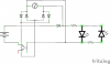
Attached is what I think might work...
because I'm installing this in a small model, I don't think I'll be able to fit it inside the loco body, as I won't be able to find a small enough relay.
I'd prefer to use appropriate 'discrete' devices, such as transistors, but I've no idea how to use them to do what I want. Could anyone give me some pointers?
What I'd like to happen :-
When there is no power to the loco from the track, the red LED should be powered, from the battery. (on my diagram, it's the left LED)
When there is power to the track, the appropriate LED should be on, powered from the source from the track.
*Bonus Points* If the circuit can keep the directional LED's lit for a short time, before dropping to red, that would be awesome!
I *think* my circuit will do that as is... Please tell me if I'm wrong. (I might need to reverse the 'track feeds' to the LEDs, depending on the specific's of the loco,)
N.B. the 'AC' Source in my diagram is used to represent a DC supply, of alternating polarity, up to a maximum of 12v, 1amp. I've also deliberately removed the part labels, as I'll work out the correct parts to use later.
Thanks in advance for any advice given.
Steve
I'm trying to design a circuit to enhance the operation of a model locomotive, so that the headlights activate on the correct direction, and switch to red both ends, if the train is not in motion.
I'm not able to use a 'DCC' method of this, as I use analogue control.
Attached is what I think might work...
because I'm installing this in a small model, I don't think I'll be able to fit it inside the loco body, as I won't be able to find a small enough relay.
I'd prefer to use appropriate 'discrete' devices, such as transistors, but I've no idea how to use them to do what I want. Could anyone give me some pointers?
What I'd like to happen :-
When there is no power to the loco from the track, the red LED should be powered, from the battery. (on my diagram, it's the left LED)
When there is power to the track, the appropriate LED should be on, powered from the source from the track.
*Bonus Points* If the circuit can keep the directional LED's lit for a short time, before dropping to red, that would be awesome!
I *think* my circuit will do that as is... Please tell me if I'm wrong. (I might need to reverse the 'track feeds' to the LEDs, depending on the specific's of the loco,)
N.B. the 'AC' Source in my diagram is used to represent a DC supply, of alternating polarity, up to a maximum of 12v, 1amp. I've also deliberately removed the part labels, as I'll work out the correct parts to use later.
Thanks in advance for any advice given.
Steve
")