Maker Pro
Maker Pro

pls explain this simple circuit

fayyaz0346

May 23, 2010
10
Joined
May 23, 2010
Messages
10
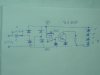
hi, this is is a cheap chines rechargable battery circuit i want to know why the transister is used. this tourch uses one single led and a set of ten leds one at time.circuit is very simple 220v ac is rectified thorugh a capacitor but i don't know the use of two extra diods and a transister. can some one explain this if full schematic diagrame is available then it would be very nice. sorry for spell mistake. thanks
 

Attachments

  • DSC00867.jpg
    DSC00867.jpg
    128.1 KB · Views: 5,218
  • DSC00882.jpg
    DSC00882.jpg
    141 KB · Views: 1,278
  • DSC00886.JPG
    DSC00886.JPG
    109 KB · Views: 1,281
Last edited:

LTX71CM

May 23, 2010
182
Joined
May 23, 2010
Messages
182
The large capacitor and resistor next to it limit current and drop the voltage available to the rest of the circuit. Four of the diodes form a full wave bridge rectifier to get a DC output from an AC input. The small electrolytic cap is likely used to smooth the DC coming from the bridge rectifier.

Do NOT use that to charge the lithium ion battery you mention in your battery monitor post. Doing so is asking to start a chemical fire. Lithion batteries are very picky about how they're charged and that needs to be observed for safety.
 

(*steve*)

¡sǝpodᴉʇuɐ ǝɥʇ ɹɐǝɥd
Moderator
Jan 21, 2010
25,510
Joined
Jan 21, 2010
Messages
25,510
You've carefully hidden some of the important details, like where the wires join up. It would also be helpful to know what the three wires on the left are for (2 I can understand, but 3?).

I suspect that the capacitor's reactance is used to limit the current to the bridge rectifier.

The rest of the circuit is probably a regulator to reduce the maximum voltage (under no load).

It's a bit scary because the whole circuit essentially operates at mains potential. I hope this is built inside something that is well insulated.
 

fayyaz0346

May 23, 2010
10
Joined
May 23, 2010
Messages
10
no i am not trying to charge the lithium ion battery from this circuit just want to know to why a transistor is used for i thought that it is for switching when ac line is cut leds lightg up.
 

(*steve*)

¡sǝpodᴉʇuɐ ǝɥʇ ɹɐǝɥd
Moderator
Jan 21, 2010
25,510
Joined
Jan 21, 2010
Messages
25,510
Perhaps if you can tell us what's written on the device (it may not be a transistor) and give us another view of the board with the connections visible, and also an image of the underside (although it's mostly visible through the board) then we could make some intelligent guesses.
 

fayyaz0346

May 23, 2010
10
Joined
May 23, 2010
Messages
10
I have uploaded two new pics but are not complete i am trying to draw full circuit schamatic but is very confusing a lot of wires pcb is very simple but wiring patren is comlecated.
transistor is S 8050
 

Resqueline

Jul 31, 2009
2,848
Joined
Jul 31, 2009
Messages
2,848
You're not making it easy for us..
Those two boards may be similar but they're not identical and it's not easy to see the pattern on the second board. Also, the transistor is of the schizofrenic type.
Your diagram is not entirely correct but that's no problem, with good pictures we can draw it for you. Some diodes are zeners. Is that battery a sealed lead-acid type btw.?
 

fayyaz0346

May 23, 2010
10
Joined
May 23, 2010
Messages
10
pls, check diagram agian i have comleted it now it will be easy for you. this circuit is quite simple i think the transistor is for switching job like when ac 220v is cutoff 10 leds lights up automaticly .
 

LTX71CM

May 23, 2010
182
Joined
May 23, 2010
Messages
182
As I said before the large capacitor and resistor limit current and serve to help get the voltage down. The four diodes on the left of your drawing form a full wave bridge rectifier to provide DC to the rest of the circuit. It appears that maybe the switch and transistor form sort of a battery tester. Press the button, if the LEDs light, the battery is good/charged. That's my guess.
 

Resqueline

Jul 31, 2009
2,848
Joined
Jul 31, 2009
Messages
2,848
Yes, that's better, but the transistor circuit still doesn't make sense by itself like that, and there are three wires to that switch. Where is the battery hooked in?
Capacitors and rectifier are ok & make sense.
 
Top