Thanks for the new diagram, it's better.
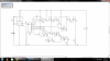
I've just noticed a mistake in the green/red connections. the green and red LEDs are swapped. You need the green and amber phases of one light to correspond with the red phase of the other light. Otherwise during each amber phase, one road will have the green light while the other road has the amber light. During the amber phase, you want the other road to have a red light, not a green light! So the red LEDs should be at the bottom of the chain, connected to the 1k resistors.
This doesn't explain why the circuit isn't working in the simulation though.
I don't know why R2 is drawn shorted out.
I don't see any problem with the design. So R1,3 and G2,4 worked. Was the 4017 advancing from one phase to the next? Everything looks right except possibly for pin 7 of the 555 being connected to pin 3. This shouldn't cause a problem but it's not normally done.