Maker Pro
Maker Pro

pic programming help - controlling GSM to send message from PIC16F873A

anroop

Dec 11, 2013
65
Joined
Dec 11, 2013
Messages
65
ya. the whole code is getting executed but no SMS is received. I think there's a problem with the code. the logic is correct, but don't know if the code is exactly correct.
 

anroop

Dec 11, 2013
65
Joined
Dec 11, 2013
Messages
65
ya it's working.
the code is fully getting executed but the sms is not received. the logic is correct, but the code might not be exactly correct. correct me if u can.
 

gorgon

Jun 6, 2011
603
Joined
Jun 6, 2011
Messages
603
ya it's working.
the code is fully getting executed but the sms is not received. the logic is correct, but the code might not be exactly correct. correct me if u can.

What is working, and how do you know it?

If you use the PIC, how is the connection between the PIC and the GSM unit?
Are you running it through a RS232 interface?
If not, do you use inverters for the TXD and RXD?

The logic signal from the PIC is inverted in the RS232 interface, and the GSM unit is running RS232 if you communicate via a COM port on the PC.
 

KrisBlueNZ

Sadly passed away in 2015
Nov 28, 2011
8,393
Joined
Nov 28, 2011
Messages
8,393
OK, as gorgon says, if the GSM modem connects directly to a COM port, you need an RS-232 transceiver IC between the PIC and the GSM modem to convert between logic levels and RS-232 levels. The transceiver also inverts the signals - transmitters convert logic low to positive voltage, and logic high to negative voltage, and receivers do the opposite.

Look into the MAX232 (or equivalents from other manufacturers).

What is the clock source for the PIC? Do you have an external crystal? If so, what is its frequency? How did you calculate the baud rate divisor to get 9600 baud?
 

anroop

Dec 11, 2013
65
Joined
Dec 11, 2013
Messages
65
I have the MAX 232 IC inbuilt in the GSM modem. I do use a external crystal oscillator 4MHz. I used to generate 9600 baud rate from reference to the Datasheet of the PIC (by specifying spbrg value). the PIC and GSm are interfaced using RS232 connector.
gorgon please refer to my previous post to see the interface between GSM and PIC.
 

KrisBlueNZ

Sadly passed away in 2015
Nov 28, 2011
8,393
Joined
Nov 28, 2011
Messages
8,393
The GSM modem probably does have a MAX232 inside it, to convert its internal logic-level signals to RS-232 levels. You need ANOTHER MAX232, on your board, to convert the RS-232-level signals back to logic levels that you can connect to your PIC.
 

anroop

Dec 11, 2013
65
Joined
Dec 11, 2013
Messages
65
ok, kris. I think that might be the mistake. I'll try it and get back to you!!
 

anroop

Dec 11, 2013
65
Joined
Dec 11, 2013
Messages
65
so it should be like this, is it!


--------------- MAX232 for PIC-------------RS232-------------------MAX232 for GSM (inbuilt)
PIC------> (Tin )MAX232(Tout) -----------------------> (Rin)MAX232(Rout) ------> GSM
 
Last edited:

davenn

Moderator
Sep 5, 2009
14,264
Joined
Sep 5, 2009
Messages
14,264
so it should be like this, is it!


--------------- MAX232 for PIC-------------RS232-------------------MAX232 for GSM (inbuilt)
PIC------> (Tin )MAX232(Tout) -----------------------> (Rin)MAX232(Rout) ------> GSM

no, the other way around
the GSM is transmitting data, the PIC is receiving data


DAve
 

KrisBlueNZ

Sadly passed away in 2015
Nov 28, 2011
8,393
Joined
Nov 28, 2011
Messages
8,393
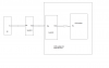
PIC TXD -----> (T.IN) MAX232 transmitter (T.OUT) -----> GSM "TXD" connection
PIC RXD <----- (R.OUT) MAX232 receiver (R.IN) <----- GSM "RXD" connection

The GSM modem, being a DCE (data communications equipment) component in the RS-232 conventions, should actually receive its data on the connection marked TXD; this connection is called TXD because it's the data transmitted by the PIC, which is a DTE (data terminal equipment, another RS-232 term), and it's also the data transmitted to the GSM network by the GSM modem.

Conversely, the data received from the GSM network by the modem should be sent out from the GSM modem on the connection marked RXD, and received by the serial port on your PIC board.

It's possible that the designers of the modem did not follow this RS-232 convention, which is very old. In that case, they may have swapped the names of the TXD and RXD signals at the GSM modem.

You can tell which way the modem is connected by just powering it up, and measuring the voltages on the two connections relative to the GND connection. One connection should have around 0V on it; this is the data input to the modem. The other connection should have a negative voltage of at least 3V on it; this is the data output from the modem.

If the negative voltage is present on the connection marked RXD, then the diagram at the top of this post is correct.

If the negative voltage is present on the connection marked TXD, then use this diagram instead:

PIC TXD -----> (T.IN) MAX232 transmitter (T.OUT) -----> GSM "RXD" connection
PIC RXD <----- (R.OUT) MAX232 receiver (R.IN) <----- GSM "TXD" connection

The only difference is that TXD and RXD at the GSM modem are swapped.
 

richardb

Dec 21, 2013
48
Joined
Dec 21, 2013
Messages
48
I would suggest that you connect your pic to a terminal, then you can make sure that the voltage is inverted correctly, the baud rate is correct and that the command is correct, also as you've already connected the modem to the terminal you then know for sure what the wiring should be
 

anroop

Dec 11, 2013
65
Joined
Dec 11, 2013
Messages
65
so, do I need to insert a MAX232 IC inbetween PIC and GSM (inbuilt MAX232) or not. I tried by inserting, but its not working
 

richardb

Dec 21, 2013
48
Joined
Dec 21, 2013
Messages
48
Yes but try using the terminal it will show you straight away what is happening, try realterm.
 

KrisBlueNZ

Sadly passed away in 2015
Nov 28, 2011
8,393
Joined
Nov 28, 2011
Messages
8,393
so, do I need to insert a MAX232 IC inbetween PIC and GSM (inbuilt MAX232) or not. I tried by inserting, but its not working
Yes. Post a schematic of what you have done.
 

anroop

Dec 11, 2013
65
Joined
Dec 11, 2013
Messages
65
Here what you asked Kris!.
Richard, I cannot catch up what you said. could you be more detailed.
 

Attachments

  • block diagram2.png
    block diagram2.png
    17.7 KB · Views: 162

KrisBlueNZ

Sadly passed away in 2015
Nov 28, 2011
8,393
Joined
Nov 28, 2011
Messages
8,393
That's right, but it's not a complete diagram. Most of the detail is missing. Pin numbers, for example.

Also you haven't connected the data in the other direction. Even if it isn't needed (yet), you should connect it.
 

anroop

Dec 11, 2013
65
Joined
Dec 11, 2013
Messages
65
the whole connection...
 

Attachments

  • whole block.jpg
    whole block.jpg
    83.1 KB · Views: 128

KrisBlueNZ

Sadly passed away in 2015
Nov 28, 2011
8,393
Joined
Nov 28, 2011
Messages
8,393
That looks right. I agree with Richard's suggestion: feed the RS-232 transmitted data into the received data connection of a serial port on a PC and run some terminal software on the PC. Set it to 9600 baud and see whether it receives the transmission from the PIC.

You can also use an oscilloscope or a logic probe to see whether there is data at the TXD output of the PIC and the RS-232 transmit output.
 

richardb

Dec 21, 2013
48
Joined
Dec 21, 2013
Messages
48
connect pin 14 on your max232 to pin 2 on the pc "d"type
connect 0v from your pic to pin 5 on the pc "d"type


download realterm

http://realterm.sourceforge.net/

set the terminal software to the correct baud rate and connect to the correct comport.

start your pic and see what is displayed
 
Top