Maker Pro
Maker Pro

Phototransistor question

Rick L

May 21, 2014
14
Joined
May 21, 2014
Messages
14
I am in the middle of a project and have some questions. The project is an electronic target that will detect a 4.5mm pellet traveling at 600 fps. When the pellet is detected it turns on an LED to signify a good shot.
My pellet detector is a white LED opposite a phototransistor. When the pellet passes between the LED and phototransistor the photo transistor output triggers a 555 set up as a one shot and an LED lights up.
I have the circuit built and functioning as described. I would like to be able to adjust the sensitivity of the pellet detector. I'm not sure what the best way to do this is. I have changed the value of the emitter resistor in the phototransistor with no real change in sensitivity. My thought is since the phototransistor is set up as a "dark on" if I turn down the brightness of the LED until the phototransistor is barely on it would be more sensitive to a pellet passing through. I haven't tried adjusting the brightness of the LED shining onto the phototransistor yet, I'm thinking a pot in series with the LED would allow me to control the current and the brightness.
Any input is appreciated.
 

Attachments

  • schematic.jpg
    schematic.jpg
    63.6 KB · Views: 162

Arouse1973

Adam
Dec 18, 2013
5,178
Joined
Dec 18, 2013
Messages
5,178
Hi Rick
When you say more sensitive. What do you mean? Do you want to increase the range between TX and RX or a faster response?
Adam
 

Rick L

May 21, 2014
14
Joined
May 21, 2014
Messages
14
I realized I didn't specify in my original post the pellets are being shot from a pellet rifle.
Forgive my ignorance, I'm not sure what TX and RX mean.
During the mockup phase of this project I was able to get this circuit to "see" pellets dependably. It was not hooked up to the 555 timer during the mockup stage, instead I had it hooked to a two transistor latch that turned on the LED.
What I am seeing with the circuit as it is now is it wont "see" the pellets consistently. While troubleshooting the circuit I noticed the phototransistor has to be almost totally blocked before it changes state. My current thought is, if the LED wasn't as bright the phototransistor would change state without having to be blocked almost totally. I may try adding a small pot in series with the LED and see if I can get less light out of it that way also I may end up trying different LEDs to see if different colors give me the response I am looking for.
 

(*steve*)

¡sǝpodᴉʇuɐ ǝɥʇ ɹɐǝɥd
Moderator
Jan 21, 2010
25,510
Joined
Jan 21, 2010
Messages
25,510
What you probably need is a constant current source feeding the phototransistor and the output being compared against a reference voltage. (The constant current source will give you a greater sensitivity than just using a resistor, and the output voltage is not determined by your supply rail.)

varying the gap between the normal (unblocked) output voltage and the reference would vary the sensitivity.

For best sensitivity, you would derive the reference from the average output voltage of the phototransistor and then add some variable offset. This would be preferable because the transistor's operating point could vary with temperature, and other variables. Deriving a reference from the output voltage ensures that drift doesn't become so much of a problem.
 

KrisBlueNZ

Sadly passed away in 2015
Nov 28, 2011
8,393
Joined
Nov 28, 2011
Messages
8,393
Thanks for the clarification. I was wondering the same things that Adam asked.

TX and RX mean transmit (or transmitter) (i.e. the LED) and receive (or receiver) (i.e. the phototransistor).

For that particular problem, a simple solution is to reduce the value of the emitter resistor.

Here's an explanation.

The phototransistor responds to light intensity by producing a roughly proportional photocurrent, or more correctly, by allowing a current to flow through it, from its collector to its emitter.

So if you connected a phototransistor across a power supply with no series resistor (don't actually do this because you could damage it if the light is bright enough), and measured the current through it, you would see the current vary roughly linearly in response to the light falling on the phototransistor.

Imagine that you subject the phototransistor to a steadily increasing light intensity. The current might start at 0.1 mA, increase smoothly through 1.0 mA, and eventually reach 10 mA.

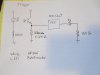
The 555's trigger input responds to voltage. So you need some way to convert the current from the phototransistor into a voltage; hence the emitter resistor.

But the combination of the supply voltage and the value of the emitter resistance sets a limit for the current that can flow through the phototransistor, according to Ohm's Law: I = V / R. In your case, V isn't specified, so I'll assume it's 12V, and R is 8.2k. That limits the current to about 1.5 mA.

Now imagine that you subject the phototransistor to the same steadily increasing light intensity. Initially, say, 0.1 mA will flow. This produces a voltage drop of 0.82V across the resistor (from a rearrangement of Ohm's Law: V = I R). There will be 11.18V remaining across the phototransistor.

The current continues to increase, following the brightness of the light source. When it reaches 1 mA, the voltage across the emitter resistor will be 8.2V. There will be only 3.8V across the phototransistor. So you can see that as the phototransistor passes more current, more voltage is dropped across the emitter resistor, and less voltage remains across the phototransistor.

Now imagine that the illumination has increased to a level that should produce 1.4 mA current in the phototransistor. 1.4 mA through an 8.2k resistor produces 11.48V across the resistor, leaving only 0.52V across the phototransistor. The phototransistor is "running out of voltage"! It cannot create voltage from nothing; as the illumination continues to increase, the phototransistor will become "saturated" - that is, it "wants to" pass more current, but its collector-emitter current is being limited by the external components (the supply voltage and the emitter resistor) and cannot continue to increase in proportion to the "input" current (the photocurrent caused by the incident light).

So as the light intensity continues to increase, the phototransistor current flattens off into a horizontal line. A typical transistor saturation voltage is around 0.2V, leaving 11.8V across the 8k2 resistor; from I = V / R, the current will be about 1.44 mA. Even when the light intensity has increased to the point where the phototransistor "wants to" pass 10 mA of current, the actual current will only be 1.44 mA, about seven times less in this example.

When a transistor is saturated, it takes a while for it to "un-saturate", because solid state physics. Something called charge storage which I don't understand, and probably other factors too. So if the phototransistor sees a rapid drop in light intensity, it won't even start to respond until the light intensity has dropped by a factor of seven (in this example), and it will respond quite sluggishly.

So in this application, you really want to avoid, or at least minimise, saturating the phototransistor. This is done by changing the external circuit so the phototransistor can pass more current. Either increase the supply voltage, or reduce the emitter resistor - the resistor is the obvious choice.

Here's what I suggest. This may be a bit simplistic but it should be a start.

1. Make your LED brightness adjustable, or just switch-settable to full brightness and half brightness, for calibrating the phototransistor. For example, if your current limiting resistor is 220 ohms, connect another 220 ohm resistor in series with it, with a switch across it. Closing the switch puts only the first resistor in circuit, giving you full brightness. Opening the switch gives 440 ohms series resistance which will roughly halve the LED's brightness.

2. Determine the minimum emitter resistance using the phototransistor's data sheet. For example if the phototransistor data sheet says the maximum rated current is 100 mA, go for half that value, i.e. 50 mA, and calculate R using R = V / I where V is the power supply voltage and I is the current in amps.

3. Replace the emitter resistor with a preset potentiometer, aka "trimpot", with a resistance of, say, 1k, in series with a resistor with the value you calculated. This is just to prevent possible damage to the phototransistor.

4. Turn the trimpot to the maximum resistance end. Set the LED to half brightness. With your detector circuit set up normally with no obstructions in the light path, adjust the trimpot until the 555 circuit triggers.

5. Return the LED to full brightness.

That should do it. It calibrates the detector circuit so it triggers when the light intensity drops to half its normal value. Since the 555 triggers when pin 2 goes below 1/3 of the supply voltage, with the LED running at full brightness you should see around twice that voltage, i.e. 2/3 of the supply voltage, on the phototransistor's emitter. In that state, the phototransistor is not saturated (there is still 1/3 of the supply voltage across it) so it should respond very quickly to changes in light intensity.

Using a lower emitter resistance also reduces the effect of capacitance, which is another delaying factor. In general, operating a circuit at a higher current makes it faster. This is why desktop computers still have a performance advantage over laptops.

If you find that variations in temperature or other factors cause the circuit to trigger when it shouldn't, you can increase the emitter resistance. This may make the detector respond less quickly though.
 

Rick L

May 21, 2014
14
Joined
May 21, 2014
Messages
14
Thanks for your help Steve and Kris, I don't have a data sheet for the phototransistor I'm using. It was purchased at Radio Shack and I am finding that they don't offer much info on the parts they sell. I'm sure a Google search will get me the info I need.
I have been referring to a "Fairchild application note for design fundamentals for phototransistors". The Application note gives two options, Active Mode and Switch mode. Switch mode sounded like what I needed for this application so I went with that.
This is the first circuit I have built in about 30 years so I need to study all the suggestions and info you guys have given me and put more thought and planning into this. I'm looking forward to the challenge.
Thanks again for your input, I'll keep updating my progress.
 

(*steve*)

¡sǝpodᴉʇuɐ ǝɥʇ ɹɐǝɥd
Moderator
Jan 21, 2010
25,510
Joined
Jan 21, 2010
Messages
25,510
Beware that using the device as a switch may mean you drive it to saturation.

There is an application note somewhere that describes how to increase the speed of optocouplers. The same principles apply to what you're doing.

As a rule of thumb, as you increase sensitivity you reduce speed. My suggestion was based on the output being in the linear range and detecting small changes.

Kris has tackled the problem from another angle. His general points about speed and emitter resistors are worth noting
 

Arouse1973

Adam
Dec 18, 2013
5,178
Joined
Dec 18, 2013
Messages
5,178
To speed up opto couplers I think you need to apply some base bias if you can connect to the base terminal.
Adam
 

(*steve*)

¡sǝpodᴉʇuɐ ǝɥʇ ɹɐǝɥd
Moderator
Jan 21, 2010
25,510
Joined
Jan 21, 2010
Messages
25,510
These are talking about optocouplers, but with one very minor difference, and two more significant differences, that's what you have.

Here, here, and here. (edit: I fixed the links)

The minor difference is that yours is somewhat larger.

The significant differences are that you're interrupting the beam (so LED delays are NOT a factor) and that it is not enclosed (so ambient lighting IS a factor).
 
Last edited:

Rick L

May 21, 2014
14
Joined
May 21, 2014
Messages
14
Thanks again for all your help you guys :). Kris if you are not a teacher you should be, your explanation cleared things up for me. I found a data sheet on the photo transistor and that gave me a starting point for my emitter resistor value.
The max collector current is 25 ma, CE saturation voltage is .4 V and I'm using a 9 V battery as a power source.
8.6v / 25ma = 344 ohms. I went with 410 ohm as the emitter resistor to keep the collector current below Max. and added a 10K Pot in series for my adjustment.
For my TX LED control I used a 510 ohm resistor in series with a 2K Pot. I can dim the LED but not turn it all the way off.
It worked great! I can detect a pellet every time now. This is the first step, the target is built on a 3/4" pine board with a two different sized washers as targets (large and small) The washers are over holes in the board and the LED and phototransistor are mounted on the back side of the board. If the pellet passes through the hole in the washer the circuit detects it and turns on a Green LED on top of the target for a couple seconds indicating a good shot.
I plan to add a second circuit. One for the smaller target (1/4") will turn on an LED and a sound effect. The larger target (1/2") will only turn on an LED. I have plans to add a piezo pick up to detect a pellet striking the board or the washer and it will turn on a buzzer, indicating a miss.
Once I get it closer to being done I'll post a video, if I can figure out how :confused:
Thanks again for your help, it's going to take a while to relearn this stuff....
 

Attachments

  • target schematic.GIF
    target schematic.GIF
    22.9 KB · Views: 143
Top