Maker Pro
Maker Pro

Photodiode falltime problem

pooya_BA

Mar 24, 2021
4
Joined
Mar 24, 2021
Messages
4
Hello
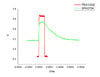
I have a problem with the photodiode. I bought the SFH 2704 photodiode and connected it directly to the oscilloscope circuit without an electronic circuit.
The fall time of this very, very long piece was about 380 microseconds, while in the information of this piece, the fall time was 67 nanoseconds.
What do you think is the problem? And how can I solve this problem?

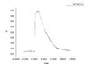
The diagram below shows the output of the photodiode with a pulse of 160 microseconds.
This pulse is taken with a commercial PDA10A2 photodiode and is exactly equal to the pulse, meaning that the light source does not have a short time.
 

Attachments

  • 1a.jpg
    1a.jpg
    100.5 KB · Views: 1
  • a2.jpg
    a2.jpg
    85.9 KB · Views: 1

Nanren888

Nov 8, 2015
622
Joined
Nov 8, 2015
Messages
622
What was the circuit that the PDA10a2 was in?
If the scope input is high impedance, then the charge on the diode junction has no path to go anywhere.
.
I vaguely remember circuits designed to keep the diode voltage at zero to minimse the effects of any junction capacitance. Probably short of that sort of thing, you might just provide a discharge path, loosing a little sensitivity for speed.
.
Any app notes or reference designs for that part?

I goggled. This page talks a little about it.
https://www.eotech.com/194/applicat...es-are-different-in-photodetector-measurement
 
Last edited:

Harald Kapp

Moderator
Moderator
Nov 17, 2011
13,745
Joined
Nov 17, 2011
Messages
13,745
Look at the test conditions in the datasheet:
upload_2021-3-24_8-13-37.png
The times given are measured with a load impedance of 50 Ω. Your scope would have 1 MΩ or even 10 MΩ, depending on the probe.
If your scope has that option, set it to 50 Ω impedance and use a direct BNC cable, no probe.

As @Nanren888 stated: usually photodiodes are operated with a load impedance near 0 Ω by using a transconductance amplifier. See e.g. the discussion here.
 

pooya_BA

Mar 24, 2021
4
Joined
Mar 24, 2021
Messages
4
What was the circuit that the PDA10a2 was in?
If the scope input is high impedance, then the charge on the diode junction has no path to go anywhere.
.
I vaguely remember circuits designed to keep the diode voltage at zero to minimse the effects of any junction capacitance. Probably short of that sort of thing, you might just provide a discharge path, loosing a little sensitivity for speed.
.
Any app notes or reference designs for that part?

I goggled. This page talks a little about it.
https://www.eotech.com/194/applicat...es-are-different-in-photodetector-measurement
Thankful
I do not know much about PDA circuitry. This is a commercial photodiode and not much is available.
 

pooya_BA

Mar 24, 2021
4
Joined
Mar 24, 2021
Messages
4
Look at the test conditions in the datasheet:
View attachment 51370
The times given are measured with a load impedance of 50 Ω. Your scope would have 1 MΩ or even 10 MΩ, depending on the probe.
If your scope has that option, set it to 50 Ω impedance and use a direct BNC cable, no probe.

As @Nanren888 stated: usually photodiodes are operated with a load impedance near 0 Ω by using a transconductance amplifier. See e.g. the discussion here.
Thank you very much
 

kpatz

Feb 24, 2014
334
Joined
Feb 24, 2014
Messages
334
There's two ways to use a photodiode. One is photovoltaic mode, where it acts like a tiny solar panel, generating a voltage when light hits it. The diode will have a slower response when used in this manner.

The other way is to reverse bias the diode, and detect current that flows when light hits it. This requires more circuitry, but allows the diode to react much faster as the capacitance is no longer a factor.
 
Top