Maker Pro
Maker Pro

Oxx Wifi Internet Radio doesn't power on

E

End3vour

Jan 1, 1970
0
My first post - I'm interested in electronics, I'm not an expert but more an amateur using common sense. I've got an Oxx Wifi Internet radio that doesn't power on:

https://cnet4.cbsistatic.com/hub/i/...44264f3f0d77d72/oxx_digital_classic_600_1.jpg

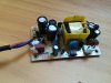
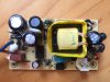
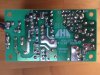
I opened it up and (I think I) established that there is some sort of fault in the circuit board (see attached photo) that transforms 240 volts to low volts. When I plug it in, my volt meter doesn't get a reading from the white connector at the bottom-right of the photo which is supposed to output the low voltage and leads to the actual radio. I do get 240 volts reading from where the power comes in.
I started testing some of the diodes and the fuse etc but really need some help as to what does what (remember Im not an expert) , what the problem might be or what to look for. The circuit board doesn't show any signs of burning. Thank you.
 

Attachments

  • IMG_6193.JPG
    IMG_6193.JPG
    208 KB · Views: 117

davenn

Moderator
Sep 5, 2009
14,268
Joined
Sep 5, 2009
Messages
14,268
hi, welcome

with mains power UNPLUGGED check the fuse in the lower left corner ... that brown rectangular part ... checking it for continuity with multimeter on Ohms range or continuity test mode

cant see any bulging capacitors ( the usual problem) but keep in mind they can fail without external signs of problems


Dave


Last edited:
E

End3vour

Jan 1, 1970
0
Thanks for your reply Dave. I have tested the fuse and that seems to be ok.
 

73's de Edd

Aug 21, 2015
3,629
Joined
Aug 21, 2015
Messages
3,629
Sir End3vour . . . . . . .

The next step then would be a power up and . . . . VERY carefully . . . . measure across the two larger E-caps to the other side of the just tested fuse.
Expecting up in the 300's of DC voltage and with no blown fuse, the 4 diodes to their left should be good.
I believe that I see an inductor hiding behind the caps, instead of it being another cap.
Finding that supply voltage present , the only other easy "fail" is that C8 ? smaller frontal feed back loop capacitor.
REALLY at suspicion, is that 8 pin frontal IC with a Pulse Width control oscillator, driver and power FET all being contained within its case.
Pass the IC number on to us for our pin out and internal schematic research.
Actually, a very good, full frame filling, close up and SQUARED up photo of the foil side may also be needed.
( Your 50 % current one is sitting askew . . .11 1/2 degrees)

Also, can you commandeer an AM pocket radio for the next phase of testing ?

( X generation and later response . . . . .What is an AM pocket radio ?)

Thasssit . . . . .


73's de Edd
 
Last edited by a moderator:
E

End3vour

Jan 1, 1970
0
Wow, thanks for you reply. Im gonna have to get back to you regarding the second part (you lost me there a bit..). Attached are two better photos.
Have tested the diodes and they are fine as you suspected. Also tested C3 and C4 and they both showed a reading (approx. 700 V?). Please let me know how to go from here.
 

Attachments

  • IMG_6194.JPG
    IMG_6194.JPG
    219.6 KB · Views: 104
  • IMG_6195.JPG
    IMG_6195.JPG
    232.7 KB · Views: 117

73's de Edd

Aug 21, 2015
3,629
Joined
Aug 21, 2015
Messages
3,629
Sir End3vour

Work on your DC voltage reading prowess, 700 VDC CAN'T be right. . . . .see the DC voltages printed on the sides of the E-caps. . . . . that is being their MAX .

Give that IC's NUMBER. and get the radio.


73's de Edd
 
Last edited by a moderator:
Top