Maker Pro
Maker Pro

Orion TV4200HD - No power.

gpatel_uk

Mar 4, 2012
40
Joined
Mar 4, 2012
Messages
40
Orion TV4200HD - power on, red, green then red light = no activity.

After the excellent help I had last time of posting I'm back! :)

I thought it would be great to learn how to fix something else. I had a look on ebay and got myself a 42" Orion TV4200HD television. It was mentioned it had sound but no picture (but the guy wasn't too sure as he had not tested it himself). Anyhow I thought for the price £15 I might as well give it a go! My first big electronics fix.

I plugged the tv in and there is no sign of power. No standby light. (i've not had chance to try it when it's really quiet to listen for any hum). ***EDIT - found master power switch and it does power up***

I'm here to have help on the process of what to do. What do I check first etc.

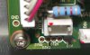
I've only had time to take of a small panel where I can see a small circuit board where the power is connected (I'll add photo's very soon). It has two copper ring things and one square capacitor. I'm guessing that is my first check to see if actual power is getting past/through this board?

I like a challenge and I do appreciate all the help from the people in this site.

Thanks - Girish.
 
Last edited:

(*steve*)

¡sǝpodᴉʇuɐ ǝɥʇ ɹɐǝɥd
Moderator
Jan 21, 2010
25,510
Joined
Jan 21, 2010
Messages
25,510
This may be an order or two more tricky, and also rather more dangerous.

The obvious thing to look at is the power supply.

Basic things like the mains fuse and power switches should be checked first.

Then look for obvious signs of "distress" -- burn marks, bulging capacitors, smoky residue, etc.

Remember that these power supplies used in devices like this can hold painful, dangerous, or even deadly charges long after the power has been removed.

Perhaps you should get yourself a "voltage detector pen" so you can probe for high voltages before you stick your finger in places that might bite. (you need one which can detect DC)
 

gpatel_uk

Mar 4, 2012
40
Joined
Mar 4, 2012
Messages
40
Last edited:

(*steve*)

¡sǝpodᴉʇuɐ ǝɥʇ ɹɐǝɥd
Moderator
Jan 21, 2010
25,510
Joined
Jan 21, 2010
Messages
25,510
Yeah, they're the thing. I'm a bit concerned about the isolation of them, but better than poking a wet finger around the place.
 

gpatel_uk

Mar 4, 2012
40
Joined
Mar 4, 2012
Messages
40
Yeah, they're the thing. I'm a bit concerned about the isolation of them, but better than poking a wet finger around the place.

Thank you! I'll get one.

I've had another look at the manual and I've just realised that there is a master power switch (a big DOH!!!!)

It is situated right under the unit. I switched that on and low and behold there is power! The standby light goes red, green then red. There are two clicks also. Kinda like a relay switch.. I've pressed the power button and nothing happens.

So the next thing to do is take the back fully off and look for any damage :)
 

(*steve*)

¡sǝpodᴉʇuɐ ǝɥʇ ɹɐǝɥd
Moderator
Jan 21, 2010
25,510
Joined
Jan 21, 2010
Messages
25,510
OK, well that tells you one, and possibly 2 things.

It tells you that it's getting power! :-D

The red/green/red may be normal, or it may be an indication of a fault. See if you can determine this from any manuals you have or from googling this device.

It may be telling you that the power supply is shutting down, and that may indicate a problem in the power supply, the circuit its powering, or even the circuit which shuts down the power supply. (this may be an evil problem)

But you do know more than you did -- and that's a positive thing.

Now that it has powered up, be VERY careful of capacitors in the power supply section. Touch them once and you'll wish you hadn't. I have no idea about the voltages used to drive the plasma display or whether it is (or remains) dangerous.

Here is the user manual.
 

gpatel_uk

Mar 4, 2012
40
Joined
Mar 4, 2012
Messages
40
I opened up the tv and took a look inside (making sure not to touch anything). I could see no visible sign of damage. I turned the unit on and watched and listened. The first thing I noticed was the board at the bottom lit up 2 rectangle LED's. The second one was solid while the first one flashed 4 times. It sounded as though it was trying to turn on but then shut down. Then I noticed a flashing green light on the main board in the middle. I counted 12 flashes in total. Next to the LED it said 'Error Position' with numbers 1-13 and a message next to each. Next to 12 it read 'D12V'. I'll google that to see what that means but at a guess that is the fault the board is saying is wrong. I've attached a photo.

I found the board http://daimelectronics.co.uk/product_info.php/products_id/1297 in case it needs replacing totally but I've seen a few youtube videos where faulty parts can be replaced.

I'll keep you up to date on where I get up to.

Thanks - Girish.
 

Attachments

  • errorposition.jpg
    errorposition.jpg
    47.2 KB · Views: 259

(*steve*)

¡sǝpodᴉʇuɐ ǝɥʇ ɹɐǝɥd
Moderator
Jan 21, 2010
25,510
Joined
Jan 21, 2010
Messages
25,510
I'd hazard a guess that it's telling you the DC 12V rail is dead or out of spec.

I would look for the 12V rail and see if there is a heatsink and some capacitors near it's output. Those would likely be the rectifiers and filter capacitors for the 12V rail.

These components are often under stress. Do the capacitors look bulgy, and has the rectifier shorted? Is there 12V on the 12V rail? I don't know if the error condition turns off the PSU or prevents the rest of the TV from starting up.

edit: that's some meaty power supply.
 
Last edited:

gpatel_uk

Mar 4, 2012
40
Joined
Mar 4, 2012
Messages
40
I'm not too sure by what you mean by 12V rail. So what I did was take a look at the board to see where it states 'D12V'. I've taken photos and attached them. One shows the main board and where 'D12V' is written. The other is the lower board that the main board connects to from the connection.

As a test I unplugged the connector from the main board that had 'D12V' on it and turned on the tv. Exactly the same thing happened, same flashing lights and same Error Position 12 flashes D12V. So to me that would mean the lower board is the one to check? As the main board error is the same with or without the lower board.

On the lower board I can't see any bulges to any capacitors. So I guess it would be the matter of checking each part now?

Thanks - Girish
 

Attachments

  • main_board.jpg
    main_board.jpg
    99.4 KB · Views: 648
  • lowerboard.jpg
    lowerboard.jpg
    120 KB · Views: 363

(*steve*)

¡sǝpodᴉʇuɐ ǝɥʇ ɹɐǝɥd
Moderator
Jan 21, 2010
25,510
Joined
Jan 21, 2010
Messages
25,510
Do you have a multimeter?

You need to check the voltages on the supply rails.

With the negative probe attached to ground, measure each of the supply rails at the test points that you have located (the small box on the first image.

It is quite possible that the power supply may be switched off by whatever it is that detects the failure, but we'll do these tests first anyway.

These tests have to be done with the power on, and parts of the board are at mains potential. BE VERY CAREFUL. Although they're not marked as such, some of those heatsinks may be at mains potential too.
 

gpatel_uk

Mar 4, 2012
40
Joined
Mar 4, 2012
Messages
40
Do you have a multimeter?

Yes I do.

You need to check the voltages on the supply rails.

With the negative probe attached to ground, measure each of the supply rails at the test points that you have located (the small box on the first image.

On the new image, you mean the negative probe in the GND hole and then the positive in the other ones? And they should read the same figures 3V, 5V, 12V?

These tests have to be done with the power on, and parts of the board are at mains potential. BE VERY CAREFUL. Although they're not marked as such, some of those heatsinks may be at mains potential too.

Yes I will be very careful!!!! :)

Thanks.
 

Attachments

  • testpoint.jpg
    testpoint.jpg
    48.2 KB · Views: 247

gpatel_uk

Mar 4, 2012
40
Joined
Mar 4, 2012
Messages
40
Ok, just done the testing.

This is what I got

5v sb = 5.2v

D3V3 = 1.1v

D12V = 0.6v

D5V = 0.0v

Is that what was expected?

Thanks.
 

gpatel_uk

Mar 4, 2012
40
Joined
Mar 4, 2012
Messages
40
I've been doing a bit more testing after reading about plasma errors. I decided to disconnect the Y-sustain board and the X-sustain board from the main board.

Both boards disconnected the tv outputs sound but no picture.

With the Y board in and X out I get the 12 flashes.

With the X board in and Y out the tv outputs sound but no picture.

I've just been reading these two pages which I'm finding very interesting:
http://blog.coppelltvrepair.com/2010/03/how-to-identify-burned-buffer-boards.html

Have checked my buffer boards as suggested in the link above and I get 39 Ohms in both directions (on both upper and lower buffer boards. But I never took them out before testing).

I have now taken out the boards and tested them.
Upper board = 41.3 Ohms both ways
Lower board = 1 (open circuit?)

I've also tested the IC's on the boards and only at one point do I get a reading the rest of the points I get 1 (open circuit again?)

http://blog.coppelltvrepair.com/2010/10/lj92-01200a-lj41-02759a-truth-according.html

Have checked the fuse on the Y board and it is ok.

Have checked the IPM STK795-518 on the Y Board and I'm getting a 'short' reading when reading the ground to another connection. Here is the link for how to test it http://blog.coppelltvrepair.com/2011/04/how-to-test-stk795-518-ysus-ipm-for.html
 
Last edited:

gpatel_uk

Mar 4, 2012
40
Joined
Mar 4, 2012
Messages
40
I've tested the supply rails again but this time with Y-Board disconnected.

5V sb = 5.2V
D3V3 = 3.47
D12V = 12.11
D5V = 5.22

So now all the boards read correct values.

So it is definitely something on the 3 Y boards???

I have also noticed some other test points on the main board labelled:
Vset, Vscan, Vg, Va, Ve and Vs. Would these be tested the same. Negative to ground etc?

This is all proving to be very interesting indeed and once again thank you for helping :)
 

(*steve*)

¡sǝpodᴉʇuɐ ǝɥʇ ɹɐǝɥd
Moderator
Jan 21, 2010
25,510
Joined
Jan 21, 2010
Messages
25,510
That's great.

If we can eliminate the power supply then we've eliminated a part that's most likely to bite you.

That link does seem to suggest that these modules can fail with shorts, and if that is what you're seeing then you may have found a potential cause.

However, it does not preclude a short somewhere else (although that may be less likely).

Are all three Y boards giving the fault? If not, can you connect 2 of them (say) and have the power supply not shut down?

These modules look to be surface mount. I presume you have no experience with these things?

The modules are available, but maybe you might want to take their advice and get them to change the module.
 

gpatel_uk

Mar 4, 2012
40
Joined
Mar 4, 2012
Messages
40
Are all three Y boards giving the fault? If not, can you connect 2 of them (say) and have the power supply not shut down?

I have checked both buffer boards and it appears as though 11 out of the 12 IC's are bad. As only along one side of a connector I get a reading. The rest stays at '1' on my multimeter. Here is how I checked.

On the main Y board the large IC is giving a '1' reading when checking against 'ground'.

Anyhow, yes I have tried 2 Y boards together (main Y with lower buffer and main with upper buffer) and still I'm getting power shut down. The only time I don't get shut down is when the main Y board is disconnected from the main board.

These modules look to be surface mount. I presume you have no experience with these things?

Yes the IC's on the buffer boards are surface mount. I will need 11 out of the 12 so depending how they will cost I might as well replace all 12. Or simply buy new buffer boards if cheaper. I've never soldered a surface mount before, all I've done is watch a youtube video of someone else doing it. I know it can be tricky.

The IC on the main Y board I don't think is surface mount as it has pins (not flat legs). The ebay link below is the one I'll need. I found it cheaper at £6.76 off ebay so I'll get one of those. I'm trying to work out how to take out the main Y board as the only way I think to get access to it is to take off the bottom part of the TV as one screw is hidden behind the AV board. A right pain in the neck! All the other screws are easily accessed.

The modules are available, but maybe you might want to take their advice and get them to change the module.
 
Last edited:

(*steve*)

¡sǝpodᴉʇuɐ ǝɥʇ ɹɐǝɥd
Moderator
Jan 21, 2010
25,510
Joined
Jan 21, 2010
Messages
25,510
If you really have 11 out of 12 dead, then I would replace the boards. However the problem may also be elsewhere, either causing these to fail, or making it look like these have failed.

I tend to be a little suspicious of widespread failures like this. It's almost as if you came out to your car one day and found three tyres and the spare all flat. Would you suspect it to be a random failure?

People with more experience might be able to tell you if this actually happens (perhaps a failure in one puts stress on another and it fails, then so does the next, and so on until almost all have failed. I wouldn't assume this without some evidence to back it up though.

Why not contact the people that do the replacement of these devices, tell them what you've found, and ask for advice?
 

gpatel_uk

Mar 4, 2012
40
Joined
Mar 4, 2012
Messages
40
Hi, I've posted some questions on some other forums but I don't think people are too interested.
Anyhow I've taken out the Y main board and checked everything (well I hope so). I've found 3 capacitors that are faulty.

2 labelled '102KS630V NP (or MP not too clear) 535PP.
1 labelled 'G-Luxon 100uf 25V'

I've found the 100uf here

I think this the other 2 here they are the same style and size but not light blue in colour.

Would both of these be OK? Should I up the spec of the capacitors to be safe they don't blow again? If so what to?

I've ordered the large IC too.

It's the buffer boards which I still need to order parts for or buy new ones now.

Thanks.
 
Last edited:

(*steve*)

¡sǝpodᴉʇuɐ ǝɥʇ ɹɐǝɥd
Moderator
Jan 21, 2010
25,510
Joined
Jan 21, 2010
Messages
25,510
Why did you think those capacitors were faulty?

Do you have pictures?
 
Top