but im not sure if they all can take 24V on the input side.
None can. The input of a photocoupler is an LED and you need to limit the current through the LEd to the vale specified in the photocoupler's datasheet. See our ressources section "
got a question about driving LEDs?"
A photocoupler will rarely be able to directly control a relay. You typically add a driver transistor in between. See our ressources section "
using a bipolar transistor to turn a load on or off". I'd expect that a relay is unnecessary in this application. Without knowing the technical data of your motor driver I cannot say more for sure. However, I'd expect the control input of the driver to be a voltage controlled signal, meaning that you apply either 0V or 5V to it and current into the input is negligible.
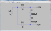
That's why I suggested you use the simple resistve divider. Or use the techniques described in the section about bipolar transistor drivers (link above) to convert the 24V signal from the PLC to a 5V signal for the motor controller.
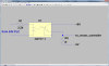
If you insist on using the photocoupler, this is how your circuit could look like:
Note that the part number for the photocoupler is a random choice, so is the value for R1. Once you get hold of a real life photocoupler, look up the required LED current in the datasheet and calculate the resistor accordingly.