Maker Pro
Maker Pro

Op Amp

kingofjong

Aug 14, 2014
30
Joined
Aug 14, 2014
Messages
30
I set up an amplifier circuit using tlc272cp op amp
I check the current using an multimeter but I don't see any gain

I was wondering if some one could tell me where I am going wrong?

I attached a picture of the circuit
 

Attachments

  • 20140814_112309.jpg
    20140814_112309.jpg
    158.2 KB · Views: 134

davenn

Moderator
Sep 5, 2009
14,263
Joined
Sep 5, 2009
Messages
14,263
Hi there
welcome to EP :)


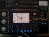
from the poor photo, there appears to be some problems with your layout

you have a resistor coming off the lower left pin of the chip to that rail that goes along the bottom of the board
BUT you also have a red wire doing the same and shorting out the resistor

that bottom rail is it the + or - rail ------ I think its supposed to be - ( negative)
meaning the top one is the positive one
You also have a blue? wire going from the pot to the top rail but that top rail isn't connected to anything else

because of the poor pic, I cannot tell what way around the chip is connected

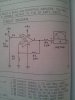
Also provide a schematic of the circuit you were trying to construct

cheers
Dave
 

kingofjong

Aug 14, 2014
30
Joined
Aug 14, 2014
Messages
30
I have attached the schematic
 

Attachments

  • 20140814_111357.jpg
    20140814_111357.jpg
    119.5 KB · Views: 131

davenn

Moderator
Sep 5, 2009
14,263
Joined
Sep 5, 2009
Messages
14,263
OK thanks for that

now you need to start rewiring you board to match the circuit :)

Dave
 

LvW

Apr 12, 2014
604
Joined
Apr 12, 2014
Messages
604
I set up an amplifier circuit using tlc272cp op amp
I check the current using an multimeter but I don't see any gain
I was wondering if some one could tell me where I am going wrong?
I attached a picture of the circuit

1.) It is not clear which current you are speaking of.
For checking the gain it is much more meaningful to measure input and output voltages.

2.) For linear amplification it is necessary to bias the opamp in its linear range. Normally, this is done using dual supply voltages with negative feedback.
You have negative feedback but single supply only. Thus the input voltage at the non-inv. opamp terminal must have a certain positive value for proper biasing. Are you familiar with biasing schemes for single supply?
 

davenn

Moderator
Sep 5, 2009
14,263
Joined
Sep 5, 2009
Messages
14,263
1.) It is not clear which current you are speaking of.
For checking the gain it is much more meaningful to measure input and output voltages.

2.) For linear amplification it is necessary to bias the opamp in its linear range. Normally, this is done using dual supply voltages with negative feedback.
You have negative feedback but single supply only. Thus the input voltage at the non-inv. opamp terminal must have a certain positive value for proper biasing. Are you familiar with biasing schemes for single supply?


all true :)
But he has to get the circuit wired properly first before worrying about actually doing measurements ;)

Dave
 

KrisBlueNZ

Sadly passed away in 2015
Nov 28, 2011
8,393
Joined
Nov 28, 2011
Messages
8,393
For linear amplification it is necessary to bias the opamp in its linear range. Normally, this is done using dual supply voltages with negative feedback. You have negative feedback but single supply only. Thus the input voltage at the non-inv. opamp terminal must have a certain positive value for proper biasing. Are you familiar with biasing schemes for single supply?
That circuit is just an experiment to demonstrate how a single-supply non-inverting amplifier with a gain of 10 (Edit: ... gain of 11...) and a reference voltage of 0V will behave as the non-inverting input voltage is adjusted from 0V to VCC. There is no need to worry about biasing. It is not supposed to amplify any signal. It is just an experiment, designed to facilitate understanding of that op-amp circuit.

Edit: We need to see a good clear picture of the used section of the breadboard, as well as the overview picture.
 

LvW

Apr 12, 2014
604
Joined
Apr 12, 2014
Messages
604
That circuit is just an experiment to demonstrate how a single-supply non-inverting amplifier with a gain of 10 (Edit: ... gain of 11...)
Sorry - I didn´t know too much about the intentions of the questioner. I was of the opinion, he wants to find a proper bias point for some further experiments.
 

KrisBlueNZ

Sadly passed away in 2015
Nov 28, 2011
8,393
Joined
Nov 28, 2011
Messages
8,393
It's one of those "100-in-1 experiments"-type kits for learning electronics by tinkering.
 

kingofjong

Aug 14, 2014
30
Joined
Aug 14, 2014
Messages
30
Okay I think I figured it out, I had the wrong wiring. I see a gain in the output when I move the resistor from the first pin to the third pin.
 

davenn

Moderator
Sep 5, 2009
14,263
Joined
Sep 5, 2009
Messages
14,263
please show us another pic of your layout
 
Top