Maker Pro
Maker Pro

Op-Amp Help

shaneyj

Jun 10, 2017
24
Joined
Jun 10, 2017
Messages
24
Hello All,
I am working on an assignment for an analog electronics course. The assignment is to take a pre-designed op amp circuit (several of them; non-inverting, inverting, adder, and differential) calculate the gain, then measure the gain of actual circuit and compare the measured results to the calculated results.

The simulation software I am using is Multisim.

The circuits are fairly simple, and they all call for the same op-amp- a LM741J.

I have completed the first 3 parts of the assignment (non-inverting, inverting, and adder), and am seeing a trend that leads me to believe that I am doing something wrong, but the assignment is so simple it seems hard to mistake(not that I'm not capable, or anything).

In scenarios where the gain is high, my measurements are capping out under where the output voltage should be.

Here is an example...

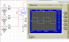
Non-inverting op amp circuit with the previously mentioned op-amp.
Vin/Freq = 4Vrms/1kHz
Rf= 5kohm
Rg=1kohm
I calculate the gain at 6... using the formula
Gain=1+ (Rf/Rg)

Simple so far, right?!

Well my measured gain is 3.15. This is an anomaly. For this type of circuit, I have a total of 5 different circuits with varying component values and the other measured values equal their respective calculated values. (This one in particular does have the highest gain, the others being 2 or less).

In my novice state, I think, "maybe this op-amp is limited and its hit its limit..."

So I move on thinking nothing of it.

But the same trend continues with inverting type (again 5 different circuits with varying component values) and it gets worse with the adder circuit. (By worse I mean I can't get higher than about 12Vrms when I calculate anywhere from 15-27Vrms.

Can anyone shed some light and help to educate me, please?

I hope you followed the scenario ok, and this is not disjointed.

Feel free to ask for clarification.

Thanks for your time!!
 

davenn

Moderator
Sep 5, 2009
14,263
Joined
Sep 5, 2009
Messages
14,263
can you please post the circuits/exercises you are working with
 

shaneyj

Jun 10, 2017
24
Joined
Jun 10, 2017
Messages
24
This is the non-inverting circuit that I calculated a gain of 6... as you can see the gain is just over 3
upload_2017-6-9_23-6-42.png

This is an inverting circuit and I calculated the gain at 5 and it is measuring at just over 3
upload_2017-6-9_23-8-48.png

Adder circuit with Vout calculated at 27.5V
upload_2017-6-9_23-9-54.png

Adder circuit, Vout calculated is 20V
upload_2017-6-9_23-10-41.png

Adder circuit, Vout calculated is 22.5V
upload_2017-6-9_23-11-16.png

Adder circuit, Vout calculated is 15V
upload_2017-6-9_23-12-0.png
 

Arouse1973

Adam
Dec 18, 2013
5,178
Joined
Dec 18, 2013
Messages
5,178
Have a look at the Data sheet. See if you can find a parameter called output voltage swing. That should help you.
Thanks
Adam
 

(*steve*)

¡sǝpodᴉʇuɐ ǝɥʇ ɹɐǝɥd
Moderator
Jan 21, 2010
25,510
Joined
Jan 21, 2010
Messages
25,510
It also may be worth looking at the input waveform compared to the output waveform.
 

shaneyj

Jun 10, 2017
24
Joined
Jun 10, 2017
Messages
24
It also may be worth looking at the input waveform compared to the output waveform.

Ch 1 (yellow) is the input.
Ch 2 (blue) is the output.

I don't think this o-scope has a small enough resolution to pick up the incoming wave.
But what does this comparison show me?
Assuming the incoming input is a sine wave, this is what I would expect to see.
Is this for verification purposes? To prove that the circuit is functioning as desired or expected? Am I missing anything?

upload_2017-6-10_6-42-6.png
 

Attachments

  • upload_2017-6-10_6-32-54.png
    upload_2017-6-10_6-32-54.png
    100 KB · Views: 53

(*steve*)

¡sǝpodᴉʇuɐ ǝɥʇ ɹɐǝɥd
Moderator
Jan 21, 2010
25,510
Joined
Jan 21, 2010
Messages
25,510
I don't think this o-scope has a small enough resolution to pick up the incoming wave.
But what does this comparison show me?

That was with the 4mV input.

Try again with the 4V input signal (or whatever was the larger value).

Also, you should be able to increase the gain on the yellow trace so it appears larger.
 

shaneyj

Jun 10, 2017
24
Joined
Jun 10, 2017
Messages
24
That was with the 4mV input.

Try again with the 4V input signal (or whatever was the larger value).

Also, you should be able to increase the gain on the yellow trace so it appears larger.

1. Interesting... The incoming signal is distorted at the zero crossing. What is the cause of this?

Also, in order to calculate the Vout, I used the formula: Vout= -(Rf/R1)*V1+(Rf/R2)*V2+(Rf/R3)*V3...
For this particular circuit with these component values I calculated a Vout of 27.7 volts- which is over the voltage output swing, as so graciously pointed out by @Arouse1973
(The values used for V in the calculation were all rms values.)

2. If you notice the output waveform, it has a pk-pk of 27.7V... Is this just a coincidence?

3. Why is the output waveform not a smooth sine?

And thank you for the dialogue... this is thought provoking and great education!

upload_2017-6-10_8-26-52.png
 

Audioguru

Sep 24, 2016
3,656
Joined
Sep 24, 2016
Messages
3,656
You are not supposed to look at the (-) input of the opamp because the signal is almost completely cancelled by the negative feedback when the opamp is not clipping. But your opamp is obviously clipping like crazy with such a high input level.You are supposed to look at the input of the entire circuit instead.
 

Audioguru

Sep 24, 2016
3,656
Joined
Sep 24, 2016
Messages
3,656
You calculated that the output should be 27.5V RMS. But the scope shows peak-to-peak (Pk-Pk) that is 2.282 times less. It is a coincidence that the numbers are almost the same.

Don't you know about clipping? When the output tries to be 27.5V RMS x 2.828= 77.77V peak-to-peak but the output swing cannot go higher than 27.7V peak-to-peak then the peaks of the waveform are clipped off so it is not a smooth sinewave anymore. When an audio amplifier is turned up too high then its clipping produces severe distortion.
 

shaneyj

Jun 10, 2017
24
Joined
Jun 10, 2017
Messages
24
You are not supposed to look at the (-) input of the opamp because the signal is almost completely cancelled by the negative feedback when the opamp is not clipping. But your opamp is obviously clipping like crazy with such a high input level.You are supposed to look at the input of the entire circuit instead.
What do you mean by "the entire circuit"? Channel 1 of the o-scope is connected to the - side of the op amp input, after the voltage source resistors, before it enters the op amp.
Connecting to the positive side, which is grounded, produces no waveform on the scope.
 

shaneyj

Jun 10, 2017
24
Joined
Jun 10, 2017
Messages
24
You calculated that the output should be 27.5V RMS. But the scope shows peak-to-peak (Pk-Pk) that is 2.282 times less. It is a coincidence that the numbers are almost the same.

Don't you know about clipping? When the output tries to be 27.5V RMS x 2.828= 77.77V peak-to-peak but the output swing cannot go higher than 27.7V peak-to-peak then the peaks of the waveform are clipped off so it is not a smooth sinewave anymore. When an audio amplifier is turned up too high then its clipping produces severe distortion.
I learned about clipping in a week's unit lesson about 3 semesters ago... thank you for the reminder, and the clarification!
 

duke37

Jan 9, 2011
5,364
Joined
Jan 9, 2011
Messages
5,364
In #13 the circuit is hidden but it looks as if it is a virtual earth amplifier. If the output clips, the amplifier cannot work properly. The only part of the waveform which is correct is that at the crossover positions.
 

shaneyj

Jun 10, 2017
24
Joined
Jun 10, 2017
Messages
24
In #13 the circuit is hidden but it looks as if it is a virtual earth amplifier. If the output clips, the amplifier cannot work properly. The only part of the waveform which is correct is that at the crossover positions.
The professor calls it an "op amp adder" circuit...
upload_2017-6-10_10-1-27.png
 

duke37

Jan 9, 2011
5,364
Joined
Jan 9, 2011
Messages
5,364
As audioguru says in #14 the signal is almost complerely cancelled at the - input. Therefore this can be considered as a virtual earth.
Current running into this position from whatever source has to be provided by the output of the amp. Thus the output current times the feedback resistor is the output voltage.
 
Top