Maker Pro
Maker Pro

Op-amp, changing LED colour!

Morgan

Jun 22, 2014
16
Joined
Jun 22, 2014
Messages
16
Hi all,

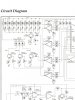
I have a Yaesu Vx7 transceiver that I want to change the backlight LEDs on. Currently they are orange, but I want to use blue. I got all the LEDs swapped over but now it's come to light(no pun intended) that blue LEDs require a higher voltage than orange. I experimented by bridging the resistors just before the LEDs, but that didn't work. Someone told me I need to change the values of the resistors around the op-amp Q3010, this is where I get lost. I've had a read up on op amps but I'm afraid it goes over my head somewhat. I have changed a couple of resistors around the amp but with no success. Voltage at the LEDs currently is 1.95v, my blue LEDs require 3.8v. LEDs in question are the 9 at the top of the schematic.

If anyone could help me out I'd be most grateful, I have attached the schematic too.

Morgan.
 

Attachments

  • image.jpg
    image.jpg
    147.6 KB · Views: 110

Harald Kapp

Moderator
Moderator
Nov 17, 2011
13,743
Joined
Nov 17, 2011
Messages
13,743
Hello Morgan,
I doubt that changing anything around the opamp will help. The LEDs are not driven by the opamp, but by transistors Q3001...Q3004.
Changing the series resistors to the LEds would be the right thing to do. Unfortunately these resistors already do have a rather small value, indicating that the supply voltage (top rail, right under the labels KEY and LCD) does not have a margin high enough to power blue LEDs.
My guess is that this voltage s around 3V or less..

If you find a higher supply voltage somewhere in the transceiver, you can diconnect the LEDs' anodes from the supply rail and connect it to the higher supply voltage.
If your transceiver has no higher voltage available, you could use a boost converter to create a higher voltage from teh lower voltage. However, you'll have to work carefully, using good filtering and shielding to avoid disturbances of the transceiver circuitry by the noise from the switching converter.
 

Morgan

Jun 22, 2014
16
Joined
Jun 22, 2014
Messages
16
Thank you for your reply Harald.

I hadn't actually noticed the +V wasn't the switched side, so the transistor & op amp actually control the -V side? So if I could find a higher +voltage and attach this to the anode, providing its 3V I shouldn't need to alter any resistors.

I will have a poke about with my meter and see what I can find. The easiest option I guess would be to find lower voltage blue LEDs, but I can't find them on RS's website.
 

Morgan

Jun 22, 2014
16
Joined
Jun 22, 2014
Messages
16
I did speak to a guy via his blog as he has completed the same conversion on the newer VX8 radio. He said he did the same thing when he owned a VX7, but can't remember how he did it!
 

KrisBlueNZ

Sadly passed away in 2015
Nov 28, 2011
8,393
Joined
Nov 28, 2011
Messages
8,393
Q3002 is used as an adjustable current sink in that circuit. It's not just a switch. The clue is the resistor between the emitter and 0V. The resistors in series with the LEDs are not there for current limiting; they're just used to mitigate the effect of small variations in characteristics between the LEDs (LEDs should not be connected directly in parallel because their forward voltages are never exactly the same, so some would draw more current and be brighter than the others).

So changing the series resistors won't help, especially if you're not seeing any illumination at all. Most likely that would be because the positive rail isn't high enough for the blue LEDs, and I agree with the second half of Harald's post - you'll need to find a higher voltage somewhere.

Edit: Re the conversion of the VX8... perhaps the VX8 has a different design!
 

Morgan

Jun 22, 2014
16
Joined
Jun 22, 2014
Messages
16
Good evening everyone.

I had another look at the radio and schematic this evening. I measured voltage between anode on one of the LEDs and a 0v and got 7.3v, that's with the backlight off. So I guess it's not the positive I need to source as that appears to be permanent? I've enclosed the full schematic as I realise it was just a partial screen-shot before.

Kris, thank you. After reading what you said about resistors in series, I found the LED write up on here too, so I completely understand that now :)

Any advice is greatly appreciated, this is one of those silly little ideas that ends up taking over my brain!!
image1-jpg.13719
 

Attachments

  • image1.JPG
    image1.JPG
    82.6 KB · Views: 219
Last edited by a moderator:

davenn

Moderator
Sep 5, 2009
14,264
Joined
Sep 5, 2009
Messages
14,264
Hi Morgan

I have edited your image, getting rid of all the big blank grey bits
but the actual image itself is a bit too small to read component names and types

Dave
 

Arouse1973

Adam
Dec 18, 2013
5,178
Joined
Dec 18, 2013
Messages
5,178
Have you connected the LEDs correctly? Just a thought, easily done.
Adam
 

Morgan

Jun 22, 2014
16
Joined
Jun 22, 2014
Messages
16
Hi Adam, yes I have, all polarity is correct and I didn't leave the heat on them too long either :)
 

KrisBlueNZ

Sadly passed away in 2015
Nov 28, 2011
8,393
Joined
Nov 28, 2011
Messages
8,393
According to the diagram on page 45 of the PDF, the positive rail should be around 13V. That's plenty of voltage; there should be no problem using blue LEDs.

In your first post you said that the "Voltage at the LEDs currently is 1.95v". Do you mean the voltage across the LEDs? Have you turned the backlight brightness setting up?
 

Morgan

Jun 22, 2014
16
Joined
Jun 22, 2014
Messages
16
Hi Kris, I measured the 1.95v across anode and cathode of one of the keypad LEDs while it was illuminated. The Li-ion battery is only 7.4v so I'm not sure how 13v is achievable, I can't find the 13v marking on the + rail either? The brightness setting is turned up full too, wishful thinking on my part :)
 

Arouse1973

Adam
Dec 18, 2013
5,178
Joined
Dec 18, 2013
Messages
5,178
I think you are going to need to supply some clear close up photos. Look at Kris's resource, in the resource section of this website on how to take decent pictures. Also part number of LEDs.

Adam
 

KrisBlueNZ

Sadly passed away in 2015
Nov 28, 2011
8,393
Joined
Nov 28, 2011
Messages
8,393
Hi Kris, I measured the 1.95v across anode and cathode of one of the keypad LEDs while it was illuminated. The Li-ion battery is only 7.4v so I'm not sure how 13v is achievable, I can't find the 13v marking on the + rail either? The brightness setting is turned up full too, wishful thinking on my part :)
It's possible to generate 13V from 8.4V using a boost converter, but running the LEDs from a 13V supply when lower voltages are available would waste power and I doubt they would do that.

Does the backlight only work when the unit is powered from an external supply? That might explain a few things.

If not, read on.

Those LEDs are driven with a regulated current. The schematic on page 45 of the PDF says that at maximum brightness, there is 1.12V across the emitter resistor, R3016, which is 12 ohms. This corresponds to about 93 mA flowing in Q3002 and that's divided (roughly evenly) into nine paths, so at maximum brightness, each LED runs at about 10 mA.

The 1.95V you measured across the original LED corresponds to its forward voltage when there's 10 mA flowing through it. If you replace all of the LEDs (you must replace ALL of them) with LEDs with a different forward voltage, the transistor will still try to feed 93 mA and each LED (if they're all the same type) will still have 10 mA flowing through it.

Here are some possible explanations I can think of for why blue LEDs aren't working.
  • Insufficient voltage on the 13V supply rail. Measure the voltage between the anode of one of the LEDs (they're all connected together so it doesn't matter which one you use) and the 0V rail. If it's less than around 3~5V, blue LEDs won't light up.
  • LEDs are connected backwards. In this case they will probably all be damaged.
  • One or more LEDs shorted out. Check for solder bridges and tiny solder shorts. If any LED is shorted out, none of them will work.
 

Morgan

Jun 22, 2014
16
Joined
Jun 22, 2014
Messages
16
Thanks again Kris. The LEDs illuminate on key press, or stay lit depending on the settings in the radio. They work whether on battery or sitting in the charger.

I should of mentioned that I refitted all the orange LEDs when I found out that the blues didn't work, so I will refit the blues at the weekend and read the voltage across anode and a 0v. Hopefully it was just a short and they will work this time, I sure hope so!

The blue LEDs I have are the following.
For keypad...
http://m.rs-online.com/h5/mobile/uk/catalog?searchTerm=700-8026&search_submit=


For display...

http://m.rs-online.com/h5/mobile/uk/catalog?searchTerm=692-1168&search_submit=


Thank you all so much for your input so far!
 

Arouse1973

Adam
Dec 18, 2013
5,178
Joined
Dec 18, 2013
Messages
5,178
I think the schematic voltages are wrong. It shows 13V going to a memory chip with maximum rating of 5V? But still not sure why the blues are not working, they should be ok.
Adam
 

KrisBlueNZ

Sadly passed away in 2015
Nov 28, 2011
8,393
Joined
Nov 28, 2011
Messages
8,393
Hmm. So it does. If you're talking about Q3034. The rail it connects to is marked 13.3V but if you follow it leftwards, it comes from the output of Q3025 where it is marked 3.0V. So that 13.3V marking is wrong.

I've had a closer look at the diagrams.

The voltage at the collector of Q3002 (driving the LEDs) is shown as 11.3~12.0V which fits with a positive rail of about 13.5V. And that rail goes into at least two regulators (Q3025 and Q3024, both of which produce 3.0V). Following that rail (called +B) along, down, and back, I see it connects to TP3015 and pin 18 of J3003.

The interconnection diagram on page 6 shows that it just connects to the RF board and the AF board. The battery and the DC input connector are on the RF board, shown on page 19, bottom left corner. When 13.8V external DC is plugged into J1003, the +B rail will be around 13.2V. But when the unit is running from the battery, it will be 7.4V. The specifications say the EXT DC voltage can range from 10V to 16V.

So the +B rail will range from about 7V (battery nearly flat) up to about 15V (maximum external DC voltage).

But even at 7V there should be plenty of voltage for blue LEDs. The collector of Q3002 should be able to pull down to 1.5V; definitely below 2V. So that leaves 5V for the LEDs and 10 ohm balancing resistors.
 
Top