Maker Pro
Maker Pro

One button power door locks

Ford5of5

Jan 8, 2016
11
Joined
Jan 8, 2016
Messages
11
Hi, this is my first post and I'm definitely an electronics novice. I've used relays in pre 1980's cars to greatly improve functions like power windows, locks, and headlights. That stuff is fairly straight forward. What I'm trying to do is make a 12v power lock system for my car that only uses a single momentary switch instead of a spdt switch. I've found a few schematics online that are similar but not exactly like what I'm trying to do using relays. I also found a few projects using a spdt relay to accomplish something similar. My big question is whether or not this is even worthwhile in terms of complexity and durability. I've never seen anything other than spdt switches for locks and windows in cars, so I'm thinking there's a reason for that. I was planning on using Bosch style automotive relays, but would an IC in a project box be any better in terms of durability?

Is this possible using a spdt realy to flip-flop the signal coming from the momentary switch? The signal would activate a spst relay to power the up function on the door lock actuator. A second push of the switch would flip the signal to activate a second spst relay to power the down function. Power door actuators have 2 terminals, one for up and one for down and then they ground to the cars chassis.

Please be gentle on an old noob, I haven't even seen a breadboard in over 25 years! lol
 

Ford5of5

Jan 8, 2016
11
Joined
Jan 8, 2016
Messages
11
Using this forum I just found out there a device actually called a flip-flop. Is this what I should be looking at? An issue that I didn't include in the first post is that this can not draw current when at rest or it will kill the car battery.
 

cjdelphi

Oct 26, 2011
1,166
Joined
Oct 26, 2011
Messages
1,166
A flip flop consumes a tiny amount of current, a car battery would run it for years though...

A non latching push button to toggle an on/off state... i'm worried about the relay, how do you make it go from locked to unlocked? Do you supply -12v to +12v?
 

Ford5of5

Jan 8, 2016
11
Joined
Jan 8, 2016
Messages
11
I don't know. Thats why I'm here, LOL!

I've seen schematics were 2 relays are wired in such a way that it creates the toggle effect that I'm looking for. The problem is that looks to me that this particular setup would supply constant power to flow instead of shutting off. I have a lot to relearn and a lot to learn to make this happen
 

cjdelphi

Oct 26, 2011
1,166
Joined
Oct 26, 2011
Messages
1,166
Ah then yeah the relays are wired up to give a combo of neg and pos 12v to lock and unlock the door...

So the flipflop changes from on to off, that's the state, and when pushed whatever that state is use a H-Bridge to lock unlock the motor(s)
 

cjdelphi

Oct 26, 2011
1,166
Joined
Oct 26, 2011
Messages
1,166
To be honest, for a beginner, a simple arduino might be better...
 

Ford5of5

Jan 8, 2016
11
Joined
Jan 8, 2016
Messages
11
I came across arduino and it looked real interesting. Problem is, I don't know what to call the function that I trying to create. The result is I don't know what to look for. Got any suggestions?
 

cjdelphi

Oct 26, 2011
1,166
Joined
Oct 26, 2011
Messages
1,166
Using a single push button, you read the buttons input state from the processor..

2 then toggle a boolean state state!=state;

If state is true, then apply +12v if false apply -12v if true (this is the job of the h-bridge ... or use 2 transistors and 2 relays)

Alternative is a flipflop ic, a debounce circuit, and i'm sure a logic gate somewhere to determine the states for the h-bridge/relays
 

hevans1944

Hop - AC8NS
Jun 21, 2012
4,880
Joined
Jun 21, 2012
Messages
4,880
I used one of these many years ago. I wasn't sure if they were still made. Mine didn't have a spiffy plastic case. The latching action is entirely mechanical. You energize one coil momentarily and the relay contacts latch to that position. Then when you momentarily energize the other coil, the contacts transfer to the other position. The coils can be energized continuously, but that is not the intent. Pulse one coil for one position and then pulse the other coil for the other position. The mechanical latching mechanism is quite clever and very simple. These things should last forever.
 

Ford5of5

Jan 8, 2016
11
Joined
Jan 8, 2016
Messages
11
I got a cold right now and I been trying to learn about latches, flip-flops and transistors. Thanks CJ, I'll get into arduno after i catch up on a bunch of terms. Thanks Hevans, ha I just got that! That sounds similar to one the schematics I looked at that used 2 relays to accomplish the same thing.
 

hevans1944

Hop - AC8NS
Jun 21, 2012
4,880
Joined
Jun 21, 2012
Messages
4,880
I got a cold right now and I been trying to learn about latches, flip-flops and transistors. Thanks CJ, I'll get into arduno after i catch up on a bunch of terms. Thanks Hevans, ha I just got that! That sounds similar to one the schematics I looked at that used 2 relays to accomplish the same thing.
The mechanical latching between the two relays is essential to minimizing power drain. No power at all is consumed until you momentarily energize either one of the two coils. Very old-school, that. But go ahead and learn about active circuits like relay latches, flip-flolps, transistors, etc. I spent months trying to wire up two relays as flip-flops before discovering the mechanically latched version.

I did learn a lot about relays but was sooo glad to eventually find a real simple solution. The mechanically-latched relays do seem to be a lot more expensive than what I paid for them in 1969, but IMHO still a bargain for your application. Wiring them for single momentary push-button switch operation will probably require an electrolytic capacitor to store enough energy to activate a coil and maybe a couple of diodes to route power from the SPST normally-open switch contacts through contacts on the relay to the appropriate coil.

Two separate up/down switches would be easier than one because you need to momentarily energize only one coil and then direct the single switch to the other coil without energizing that coil before you release the switch. That's where the capacitor and diodes enter the picture. Let us know if you want to go that route and perhaps I or someone else will draw a circuit for you. You can do this with two ordinary relays too, but the latching action will require a continuous power drain for the last relay coil that is energized.
 

hevans1944

Hop - AC8NS
Jun 21, 2012
4,880
Joined
Jun 21, 2012
Messages
4,880
And how does this consume no power when the relay is left energized?
An issue that I didn't include in the first post is that this can not draw current when at rest or it will kill the car battery.
 

Ford5of5

Jan 8, 2016
11
Joined
Jan 8, 2016
Messages
11
Power door locks are usually constant 12v not keyed 12v.

The way I've updated 12v power door locks in the past is to power the circuit directly from the battery with an inline fuse. Since it's a coupe, there would only be two relays for lock and unlock, a single spdt switch and 2 lock actuators. Generally, it's better to bypass the car's factory fuse block as they are decades old; this particular project is from 1979 Firebird. I did this to a 1966 Thunderbird and that was an absolute nightmare. Running current through switches the way they did back in the day burns them out. On top of that, some car as late as the 60's still used the gas-cloth sheathed wires. The sheathing gets brittle, bullet connectors seize up and connections break quite easily.

Hevans, I like you idea with the latching relay. I want to use light bulbs as an example, they are easy for me to visualize. Two bulbs, one red and the other green, wired to the latching relay and a momentary switch. In their normal state both lights would be off. If I hit the button the red light comes on and when I release the button the light goes out. When I hit the button a second time the green light comes and goes out when I release the button. Will a mechanical latch relay do that?
 

Bluejets

Oct 5, 2014
6,926
Joined
Oct 5, 2014
Messages
6,926
:oops:
The signal would activate a spst relay to power the up function on the door lock actuator. A second push of the switch would flip the signal to activate a second spst relay to power the down function.

Two bulbs, one red and the other green, wired to the latching relay and a momentary switch. In their normal state both lights would be off. If I hit the button the red light comes on and when I release the button the light goes out. When I hit the button a second time the green light comes and goes out when I release the button.

I believe these may be two different requirements.

So do you now require the latter..?

Could work with Arduino ok and I can think of a hardware arrangement that would work "in a fashion".

The previous latching relay "coils" may well not draw any current but unless there is some form of limit break switch somewhere in the load of the latching relay, it then will continue to draw current.

( If I decipher this correctly)

EDIT:- On further thinking, Hevans1944 arrangement should work if you power the pulse coil and the load via the same push button switch.:oops:
 
Last edited:

Ford5of5

Jan 8, 2016
11
Joined
Jan 8, 2016
Messages
11
Keep in mind that I'm a 40 year old noob that liked sticking stuff in electrical outlets when I was a child. When I was a teen, I always used my teeth to strip wire for my model railroads. In my 20's, I used paperclips and 9v's as cigarette lighters. LOL!

Bluejets, both of the quotes above should be the same circuit. At least in my mind they are, but refer to my previous paragraph. :D The second quote was me trying to explain in my ultra layman terms, simply replace the light bulb with up or down actuator. Most of the set-ups that I have found researching this project do not turn off what they are running when the button is released and that is my major stumbling block. In the first quote, the relays are there so that full current doesn't go through the switch, the way older cars are wired; the latching relay could probably take their place.

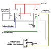
Attached is a schematic I downloaded that shows how I've done this in the past. It's not my design or idea; this mod has been around the car community for quite sometime and can really wake-up old locks and power windows.trim.jpg
Ultimately, all I'm trying to do is replace the spdt switch with a single spst. This whole idea may be too clever by half and if it is, tell me!
 

Bluejets

Oct 5, 2014
6,926
Joined
Oct 5, 2014
Messages
6,926
Ok..... enclosed are 3 circuits.

Circuit_1 was how I saw your first requirement.

i.e.The signal would activate a spst relay to power the up function on the door lock actuator. A second push of the switch would flip the signal to activate a second spst relay to power the down function.


Circuit_2 was how I saw your requirement in #16.
This is similar to your circuit #18 but with one switch instead of two.

i.e. Two bulbs, one red and the other green, wired to the latching relay and a momentary switch. In their normal state both lights would be off. If I hit the button the red light comes on and when I release the button the light goes out. When I hit the button a second time the green light comes and goes out when I release the button.

This is similar to your circuit #18 except load current is going through the switch in mine which is what you do not want.


So change circuit_2 to circuit_3 to overcome this.(additional relay operated by the switch)
Must add that Hevans1944 had a better insight to what you required. I didn't have my minds eye screwed in properly at the time.o_O

I take it you can convert to your style of drawing..??

Could also be done with transistors etc. but relays seem to be the preferred way for you.
 

Attachments

  • Circuit_1.jpg
    Circuit_1.jpg
    38.9 KB · Views: 158
  • circuit_3.jpg
    circuit_3.jpg
    48.1 KB · Views: 147
  • circuit_2.jpg
    circuit_2.jpg
    38.8 KB · Views: 172
Last edited:

hevans1944

Hop - AC8NS
Jun 21, 2012
4,880
Joined
Jun 21, 2012
Messages
4,880
It has been a while since I experimented with mechanically latched relays but they work exactly as you have shown in your diagram. The only difference is the contacts of the last relay to be actuated stays in the actuated position after power is removed from the coil. You want this to happen but you also want the power to the door actuators to be removed when the push-button is released. You want the power to the contacts to go away when the push-button switch is released. Shouldn't be a problem.

The problem is coming up with a way to store enough energy in a capacitor to momentarily operate the appropriate relay coil each time the push-button switch is actuated. I am "pretty sure" I have done this before by routing a charged capacitor through contacts on both relays, perhaps with the aid of two diodes. Pressing the button discharges the capacitor into the appropriate coil, but the capacitor doesn't re-charge until after the button is released. There needs to be just enough energy stored in the capacitor to cause the selected coil to energize (discharging the capacitor) and then de-energize with a single button press. This will cause the contact positions to change on both relays as one actuates and the other de-actuates mechanically. The next button-press routes power to the other relay coil, the capacitor re-charging only when the button is released.

Let me think about this and try to recall how I did this in the previous century.
 
Top