Sir noquacks . . . .
Methinks that you flipped a digit on the units model number., with it being a GDA-3209-1.
Soooooo . . . . . does this mean that you have a '70ish vintage house that this unit was initially installed in, and is still working fine
with the manual switch .
You just now want to get the
ORIGINAL ! . . . . .remote working.
Using this referencing . . . you can see that it is operating on the 27 Mhz citizens band with different tone modulation options
to permit like units of neighbors from self interfering.
If . . . MY . . . . unit to fix I would initially check to see if any battery contacts or corrosion effects are present and install a new battery.
And on this vintage of unit, it might have actually used silver contacts / or flashing on the units
PRESS switch . . . and after 50 years,
it just might have a BLACK . .silver oxide . . .covering them. Mildly burnish to clean them up, for positive contact again.
(NO that's not 40 grit alum oxide sandpaper, pull-thru strips for burnishing, more like #1000.)
Then you see if you have, or have access or can seek out access to use a CB radio receiver .
Transmit with the remote hand unit and seek out the specified frequency and listen for it being received, and remember that those 5-6-7-8-9-Khz
tone modulation frequencies are quite a bit higher than you usually are hearing . . . .with the highest key on a piano going out at 4.186Khz.
With no CB receiver being available, you resort to having or getting use of a communications receiver that is capable of covering the 26-27 Mhz AM spectrum.
NOW FOR THE STRAIGHT POOP ON THAT TRANSMIT UNIT OF YOURS . . . . AND NO MORE OF THE WILD GUESSES ALREADY SEEN.
Your units encoded alpha-numerics of D3 suggest of a "D" frequency on the list of the LINK posted below . . . and that is marked in with an illegible entry !
But in looking at these units frequencies and then comparing them tor CB channel frequencies, it shows that:
26.995 is being halfways between CB channels 3 and 4
27.045 is being halfways between CB channels 7 and 8
27.095 is being halfways between CB channels 11 and 12
* * * 27.??? is illegible, but it HAS to be located between the above and below channels, making it be 13 and 14 ***
27.145 is being halfways between CB channels 15 and 16
27.255 is being halfways between CB channels 25 and 26
So your unit should fall on that D frequency slot above and be putting out a 9Khz audible tone.
So put that unit up into a kissing distance of a CB receivers antenna and tune to channel 13 and then 14 on a CB receiver and expect it to be able to " bleed" thru closely adjacent frequencies and get right into that receiver, with it being that close.
Now, if you have NONE of my suggested receiver capabilities being listed above.
You find your local TRUCKERS
TRUCKSTOP . . . . and locate a trucker in or near his rig and and . .say
HEY ! . . . Good buddy . .got your ears on ?.
Yep . . . . . I shore do !
Well . . . . can we make a signal check on Channels 13 and 14 ?
Then you do your thang . . . as described . . . . usually with the antenna(s) being near one or both of the side mirrors.
You might also try
all of the possible CB frequencies / channels above.
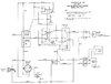
I looked at the receiver design and see that it is consisting of a full blown superheterodyne receiver to be demodulated and use DC drive to a relay that has its contacts shunting across where your manual switch also goes.
I would go into detail on a breakdown of that units operation, if it seems that the problem is not being that expected hand unit / transmitter.
HOWEVER . . . receiver wise . . .
You just said . . . . . . .
I measured about 7 volts AC at the terminals.
Look at page 3 of my reference and you will see that the 2 screw terminal block, is what gets shorted to manually trigger door operation with a shorting across them to activate the opener manually . . . . usually being run with door bell gauge of wire to the indoor pushbutton / lock..
I would expect a
full 24VAC being across it, with almost no loss with conduction thru the relay coil .
Confirm your voltage
again, as it is coming from transformer #1 secondary, so measure across that secondary directly . . . . . if still low confirm your meters AC functionality . . . by measuring the full 120VAC line voltage.
SCHEMATIC OF HEATHKIT . . . . . GDA-3209 . .Hand Transmitter and Receiver . . . .with frequencies of different xmitters codes.
https://www.rsp-italy.it/Electronics/Kits/_contents/Heathkit/Kits/Heathkit GDA-3209 Deluxe garage door opener.pdf
73's de Edd . . . . .
. . . . . . . . . . .
Fun Activities . . . .
During rush hour, sit in your parked car and start swinging a hair dryer out the window, towards faster moving /unaffected oncoming cars . . . . then see if their brake lights don't come on IMMEDIATELY , and that they then drastically slow down.