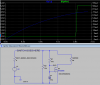
OK, take a look at this circuit diagram (schematic) and voltage and current graphs.
This is probably the simplest solution. Q1 is an N-channel MOSFET. It works like an electronically controlled switch. When the voltage between its gate terminal (the left hand connection) and the source terminal (the bottom connection) reaches a certain voltage, called the gate threshold voltage, it begins to conduct current between its drain terminal (top) and its source (bottom). This completes the circuit between the battery (shown at the left, as "V1") and the igniter.
Resistor RT and capacitor CT produce a rising voltage at Q1's gate terminal. This is because CT acts a bit like a rechargeable battery; current flows from the positive supply rail, through RT, into CT, and causes the voltage across CT to increase. After a certain amount of time, this voltage reaches the gate threshold voltage of Q1 and Q1 turns on and fires the igniter.
The graph above the schematic shows the voltage on Q1's gate (the blue trace), and the current through the igniter (the green trace, which uses the markings on the right side of the graph area), plotted against time on the horizontal axis. The start of the graph is when the switch is turned on. (The switch isn't shown in the schematic, but the place where it goes is marked.)
You can see how the gate voltage increases, starting from zero when power is first applied to the circuit. It's not a straight line. And you can see that when the gate voltage reaches about 4.3 volts, Q1 turns ON (starts conducting) and the igniter current ramps up quite quickly to the maximum current.
RD is there to ensure that CT discharges (eventually) when power is removed from the circuit.
That's the basic explanation, but there's a lot more to it.
1. Battery current capacity and igniter current
The battery needs to be able to comfortably supply the current required by the igniter, without its voltage dropping too much. You mentioned you're using coin cells; these usually have a high internal resistance and a fairly low maximum current output. They would only be suitable if the igniter is designed for low operating current, i.e. it has a fairly high resistance.
I've assumed that the igniter has a resistance of 60 ohms so it will draw 100 mA (0.1 amps) at 6 volts (this is calculated using Ohm's Law, I=V/R, where I is current in amps, V is voltage in volts and R is resistance in ohms; if you're not familiar with Ohm's Law, you definitely should be - use Wikipedia or Google).
I've also assumed that the battery's internal resistance is 6 ohms. This means that the battery voltage will drop to about 5.4V when the igniter is activated, and the igniter current will be only about 90 mA.
You should look up the specifications for the cells you're using and the igniter you're using, to see whether you need to use bigger cells. If you don't, you may not get reliable ignition, and your cells may wear out quickly.
2. Q1 gate threshold differences and variations, and suitable part numbers
In the simulation, Q1 starts to conduct at a gate-source voltage of about 4.3V. The gate threshold voltage of a MOSFET that you buy is not well-defined; it varies between units and between production batches, and it can be quite different with different part numbers.
The MOSFET I used in the simulation, BSC something, is just one that was available with the simulation software I use (this software is called LTSpice). I don't recommend that part for this application.
I've suggested a MOSFET called NTD4906N, which is cheap (USD 0.57 from Digikey) and small and has a very low ON-resistance, so very little voltage is dropped across it when it's ON. But its gate threshold voltage is roughly about 2.4V, not 4.3V. This means it will turn on earlier, at about 0.8 seconds. To adjust for this, you need to adjust the time constant, by changing RT and/or CT. See later for details.
You can actually use a wide variety of MOSFET devices in this circuit. The only important specifications are that it needs to be an N-channel MOSFET, with appropriate voltage and current capabilities. That is, Vds (maximum voltage across the top and bottom terminals) should be at least 10V, Id (maximum current through it) should be at least a few amps, Rds(ON) should be low to minimise voltage dropped across it when it's ON, and the gate threshold voltage, Vgs(th), should be between roughly 1V and 4.5V. If the gate threshold voltage is much higher than 4.5V there may not be enough voltage available to turn it on fully.
You can search on Digikey (
http://www.digikey.com) or Mouser (
http://www.mouser.com) if you're in the U.S., or Farnell/Element14 in the UK, or Jaycar in Australia. Digikey and Mouser will ship internationally, of course, but they charge an arm and a leg!
Also, MOSFETs are static-sensitive and should be handled carefully until they're connected into your circuit. Google those keywords for specific advice.
3. MOSFET heating
MOSFETs are normally used as switches. That is, they're either OFF (not conducting current through their drain-source path) or ON (conducting). This means that they dissipate relatively little power, and therefore don't get very hot.
The formula for power dissipation is P = I V, where P is power in watts, I is current in amps (that is, current through the MOSFET) and V is voltage in volts (that is, voltage across the MOSFET, i.e. between its drain and its source).
When the MOSFET is fully OFF, there may be voltage across it, but there's no current through it, so I*V is zero (or close to it). When the MOSFET is fully ON, there may be current through it, but there's no voltage across it (or very little voltage), so I*V again is close to zero.
The problem occurs when the MOSFET is not FULLY conducting. This happens during the angled ramp-up on the green trace in the graph. During this ramp-up period, the MOSFET is partly conducting (it's said to be "in its linear region"), and it has voltage across it, AND current through it. This causes it to dissipate power during this time, and this power is dissipated as heat.
As long as the time spent in the linear region is short, the thermal energy will not accumulate, and the MOSFET will not be damaged. I am assuming (hoping) that the time spent in the linear region will be short enough, and the MOSFET current will be low enough, that the MOSFET will not be damaged. I can't really know, until I know more about the igniter's characteristics. A part number for the igniter could really help here.
This is a shortcoming of this circuit. To keep it simple, I connected the R-C timing circuit straight to the MOSFET's gate, without any kind of "cleaning-up" circuit to make the MOSFET switch quickly from fully OFF to fully ON. This forces the MOSFET to run in its linear region for a short time. I could have added more components to produce a clean control signal for the MOSFET. If you like, I can show you a modified circuit that does have this feature. Let me know if you want to see it.
4. Delay time period
The delay time is determined by the MOSFET's gate threshold voltage, and the values of RT and CT. An R-C (resistor-capacitor) circuit like this can be summarised by its "time constant", measured in seconds, which is the product of the resistance and the capacitance, i.e. T=RC. In this formula, R is in ohms, and C is in FARADS, not microfarads. So the time constant of a 47k resistor and a 33 uF (microfarad) capacitor is:
T = 47,000 ohms * 0.000033
= 1.55 seconds.
This figure, 1.55 seconds, is not simply the time delay before the MOSFET turns on. That time depends on the gate threshold voltage of the MOSFET. If the MOSFET has a low gate threshold voltage, it will turn on sooner, because the threshold voltage will be reached sooner as the capacitor charges up. If the MOSFET has a high gate threshold voltage, it will turn on later. If the MOSFET gate threshold voltage is 63% of the power supply voltage (that is, the voltage at the top end of RT), then the delay will be 1.55 seconds, as calculated from the time constant formula, T=RC. This 63% figure is one of many numerical constants, like pi and sqrt(2), that are used in engineering.
The point of all of that is that given a fixed gate voltage threshold, the delay time is proportional to the time constant of RT and CT, which is T=RC, so increasing either of them will increase the delay, and vice versa.
Once you choose a MOSFET and build up the circuit, you can measure the ACTUAL delay time, and if it's too short, you can increase the time constant (by increasing RT and/or CT) proportionally, to get the delay you want.
Sorry this is so long. You said you were a noob so I've tried to cover all the bases. You'll probably want to read it a few times!