Maker Pro
Maker Pro

Need help with a PSU schematic

KrisBlueNZ

Sadly passed away in 2015
Nov 28, 2011
8,393
Joined
Nov 28, 2011
Messages
8,393
Right Duke. I added a comment to my earlier post because I realised that the reverse voltage across C9 and C10 is limited to two diode drops by the combination of diodes in BR1 and BR2. I agree that separate diodes across C9 and C10 aren't needed.
 

solo2racr

Aug 21, 2013
142
Joined
Aug 21, 2013
Messages
142
I found a .lib file for the LM317 to run in LTspice. I also have a LM317 calculator. Problem is, I am getting two different output voltages for the same resistors. Which should I believe? I tend to want to believe the LTspice output simple because it is taking into account the whole circuit where as the calc is only working from the numbers in a perfect world.

I also used the same .lib file for the 48vdc rail. Seems to work fine as a LM317HV reg as well. I never could find a good .lib file for a LM337 though.

Should I believe the calc or LTspice?
 

(*steve*)

¡sǝpodᴉʇuɐ ǝɥʇ ɹɐǝɥd
Moderator
Jan 21, 2010
25,510
Joined
Jan 21, 2010
Messages
25,510
What is the difference between your calculated voltage and what LTSpice is giving you?
 

solo2racr

Aug 21, 2013
142
Joined
Aug 21, 2013
Messages
142
With the same resistors, on the 48vdc rail and adjusted to be right in LTspice, I get 48.1vdc in LTspice and with the calc I get 49.5vdc. The +/-15vdc rails are the same but not as a drastic difference. 15.1vdc with LTspice versus 15.6vdc with the calc. Could it be that Vref is set to calculate differently between the .lib file and the calc?
 

(*steve*)

¡sǝpodᴉʇuɐ ǝɥʇ ɹɐǝɥd
Moderator
Jan 21, 2010
25,510
Joined
Jan 21, 2010
Messages
25,510
The difference is probably due to the voltage drop across the diodes.

The voltages are all going to change once a load is applied anyway.

(I presume we're talking about the bridge rectifier and filter capacitor circuit a page or so back? Because you're not going to get 48V out of an LM317)

9417d1377578469-need-help-psu-schematic-test-schem.jpg
 

solo2racr

Aug 21, 2013
142
Joined
Aug 21, 2013
Messages
142
I dropped the diodes across C3 & C4. R1, R2, R3 are there to simulate the load. I used the standard .lib file for the LM317 for the LM317HV that I will use. Here is a pic of the sim schematic.
 

Attachments

  • LT SIM LM317 TEST.jpg
    LT SIM LM317 TEST.jpg
    121.6 KB · Views: 85

(*steve*)

¡sǝpodᴉʇuɐ ǝɥʇ ɹɐǝɥd
Moderator
Jan 21, 2010
25,510
Joined
Jan 21, 2010
Messages
25,510
With those resistor values the calculated output voltage of the LM317 (U2) is something like 49.55V

What's the input voltage? It would have to be around 52V for that to work.

If you want 48V then the resistors should be something like 180R and 6k8 (gives you 48.5V). That still requires at least 50.5 V in.

220R and 8k2 gives you 47.8V.
 

solo2racr

Aug 21, 2013
142
Joined
Aug 21, 2013
Messages
142
Here is the sim for the pre regulator voltages.
 

Attachments

  • LT PRE REG VOLT.jpg
    LT PRE REG VOLT.jpg
    139.7 KB · Views: 141

(*steve*)

¡sǝpodᴉʇuɐ ǝɥʇ ɹɐǝɥd
Moderator
Jan 21, 2010
25,510
Joined
Jan 21, 2010
Messages
25,510
OK, some calculations suggest that your simulator is using 1.24V as the output voltage of the adjustable regulator and you are using 1.25V.

The specs say the actual voltage can vary from 1.2V to 1.3V, so the output voltage could vary from 47.5V to 51.5V. That's a reason to put a trimpot in there. (6k8 and a 4k7 trimpot would give a good range of adjustment.)
 

solo2racr

Aug 21, 2013
142
Joined
Aug 21, 2013
Messages
142
I remember asking about using trimmers before and was told no, don't bother.
 

(*steve*)

¡sǝpodᴉʇuɐ ǝɥʇ ɹɐǝɥd
Moderator
Jan 21, 2010
25,510
Joined
Jan 21, 2010
Messages
25,510
Well, the variation is only a couple of percent, and it's generally not worth worrying about.

In addition to that, the variation in 317's is going to be typically much smaller than the range they give for min/max.

The main reason for a trimmer is because you may not get a combination of resistors which gets you as close as you want. The bonus is that it allows you to adjust the value more precisely,

The variation between what you calculate and what LTSpice gives you is within the range of real-world tolerance.
 

solo2racr

Aug 21, 2013
142
Joined
Aug 21, 2013
Messages
142
More progress. I finally have the 1U rack mount enclosure built. Attached are a couple pics. But I do have a question regarding the transformer mounting. Here is a link to the datasheet for it as well. http://www.hammondmfg.com/229.htm Does it need to be isolated from the chassis, like mounted onto plactic, or can it be solidly mounted, metal to metal to the chassis? With the exception of the back plate, the chassis is all aluminum.
 

Attachments

  • PSU enclosure1.jpg
    PSU enclosure1.jpg
    46.8 KB · Views: 94
  • PSU enclosure2.jpg
    PSU enclosure2.jpg
    65.6 KB · Views: 93

(*steve*)

¡sǝpodᴉʇuɐ ǝɥʇ ɹɐǝɥd
Moderator
Jan 21, 2010
25,510
Joined
Jan 21, 2010
Messages
25,510
The most important thing is that the earth connection is solidly connected to the metal chassis.

The transformer looks like a PCB mount and so, no, it probably does not connect directly to the chassis.

But your PCB will need to be mounted in the chassis. Typically this is done with posts. Be sure to provide ample clearance for mains connections and preferably place a shield between the mains part of the PCB and either/both the case and areas you can poke with your fingers when the top cover is removed.
 

solo2racr

Aug 21, 2013
142
Joined
Aug 21, 2013
Messages
142
Yea, it's a PCB mount style. But I have to mount it to the chassis through the 4 holes. I'm just not sure if it needs to isolated (plastic) or if I can mount it solid (metal) to the chassis. I was going to solder wires directly to the posts on the transformer and bypass the PCB part. But the time I open either the stripboard holes or perfboard holes, neither have enough copper left to work with. The posts are .040" square.
 

(*steve*)

¡sǝpodᴉʇuɐ ǝɥʇ ɹɐǝɥd
Moderator
Jan 21, 2010
25,510
Joined
Jan 21, 2010
Messages
25,510
The page you linked to shows no holes or mounting lugs on the transformer. It is held in place by its leads.

If the transformer you have looks different, post some pictures here.

Or are you saying the leads are very thick?
 

solo2racr

Aug 21, 2013
142
Joined
Aug 21, 2013
Messages
142
The pins on the transformer are big. Very big. I tried to ream out one hole and opened it as far as I dared to and the pins still wouldn't go through.

I guess the PDF drawing shows the holes better. The PDF datasheet is to big to attach. Here are pics of both the top and bottom. You can see 4 holes (2 on either side) that go through the laminate. I am thinking solid aluminum posts that goes through the holes in the laminate would be fine.
 

Attachments

  • tranny bottom.JPG
    tranny bottom.JPG
    125 KB · Views: 107
  • tranny top.JPG
    tranny top.JPG
    131.1 KB · Views: 81

(*steve*)

¡sǝpodᴉʇuɐ ǝɥʇ ɹɐǝɥd
Moderator
Jan 21, 2010
25,510
Joined
Jan 21, 2010
Messages
25,510
OK, it seems a lot larger than I expected.

Drill out the holes in the board and if you drill out all the copper, solder a wire to the track and then wrap it around the post.

I would be concerned about veroboard tracks being able to carry the current too!

Given the size of the transformer, perhaps you need to mount the transformer to the case. (more than perhaps, I think). the laminations can be safely earthed in this case, so a hard conductive connection to the chassis would be OK. If it's insulated that would be OK too, but then I would consider earthing the laminations just in case there's a failure and it becomes live.
 

solo2racr

Aug 21, 2013
142
Joined
Aug 21, 2013
Messages
142
It's dimensions are 2.25" x 2.87" x 1.25". What I was going to do was mount it so that the pins are on the top. Solder the wires directly onto the pins and have a insulating shield inside on the top cover of the chassis. I am also going to heat shrink over where the wires are soldered to the pins. My main concern was whether or not grounding the laminates, through mounting, to the chassis would pose any problems. It seems to me that the only time when that would be the case is if the windings should ever ground to the laminates. But, that's what the fuse on the primary side is for. I just wanted to be sure before I possibly screwed up.
 

solo2racr

Aug 21, 2013
142
Joined
Aug 21, 2013
Messages
142
PROGRESS! (sort of. more on that farther down) I have it built, for the most part. But, what I am getting isn't the same as the sims in LTspice. Each of the AC secondaries measures, no load, at 24.6vac. After the rectifier, I have +/- 33.4vdc to be used for the +/- 15vdc rails and 100.4vdc to be used on the +48vdc rail. Of course this is all rms AC voltage. By the numbers, these are correct DC voltages. 24.6 x 1.4 - the voltage drop from the diodes for the +/-15vdc rails and 24.6 x 3 x 1.4 - the voltage drop from the diodes for the =48vdc rail.

The 100.4vdc going into the LM317HV is getting real close to the in/out voltage differential of 60vdc. 108vdc being max. Will this be a problem?

I bad part is that I screwed up while testing the outputs and the 48vdc wire coming out touched, I believe, ground and fried the LM317HV. All I am getting now is 1.2vdc out (ref v.) Looks like I need to place another order to Mouser. At least I can now get proper connectors going from the PSU to the mixer.

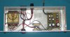
Attached is a pic of the almost complete PSU.
 

Attachments

  • MIXER PSU COMPLETE.JPG
    MIXER PSU COMPLETE.JPG
    113.8 KB · Views: 127

(*steve*)

¡sǝpodᴉʇuɐ ǝɥʇ ɹɐǝɥd
Moderator
Jan 21, 2010
25,510
Joined
Jan 21, 2010
Messages
25,510
Can you refresh our minds as to what voltages spice was predicting vs what you are getting.

It seems to me that 33V to a regulator used for a 15V rail is a bit excessive. (the regulator will dissipate as much power as is passed to the circuit. That's OK for a very small current, but not if you've got a significant load.

An LM317 giving you 1.2V is just what you expect. that is the voltage you should always see between the ground connection and the output.

It always pays to have one or two spares of parts... just in case.
 
Top