Hi,
Got this el cheapo China made ATX psu Sunshine Model NS235W from a garage sale.
The owner does not know the psu condition. When I got home, since there is no sign of
burn marks and fuse tested with continuity, I plugged in to mains, I replaced the fuse
by a 60w light bulb and shorted the output green wire to black wire.
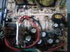
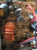
all I got is 5V DC from the purple and black output wire on the white plastic connector, I got No power from both the yellow 12V rail or the orange 3.3V rail. At first I suspect the primary side trans must have shorted. But using DMM diode test on the 3 trans with label C5027,and two trans with label C2335F shows no shorts.
The green thermistor SCK084 reads 10.6 ohm, this should be good as well.
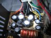
Then I diode test on secondary side schotty diode with label PSR16C40CT and S10C40C
and DMM still show no shorts. My way of test is by putting black probe to middle pin, then red probe to left pin,then to right pin; DMM reads 79.
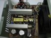
The two big Main caps measured 155VDC each. The 16 pin IC KA7500B reads 23.4VDC during
mains AC on while red probe to pin 12 and black probe to pin 7 ground.
I have replaced the small cap at C27,C33,C40 & C45 with low ESR same voltage type.
Also replaced 4 caps at yellow 12V rail, but only the 5VSTB power is on.
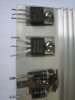
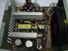
Then checking the C945 NPN trans,looking at the front side of tran,the left pin is emitter (E),
middle pin is collector(C), right pin is base(B), I unsolder the 3 trans from Q12,Q13,& Q7.
Testing by diode test,black probe to B,then red probe to E,red probe to C ;DMM reads infinite.
Then red probe to B,black to E; DMM=626 while black probe to C; DMM=624. I got almost
similar reading off circuit on all 3 trans.
What part/s is the next suspect to repair the no power from 12V and 3.3V rail? Appreciate for any help and thanks in advance.
Got this el cheapo China made ATX psu Sunshine Model NS235W from a garage sale.
The owner does not know the psu condition. When I got home, since there is no sign of
burn marks and fuse tested with continuity, I plugged in to mains, I replaced the fuse
by a 60w light bulb and shorted the output green wire to black wire.
all I got is 5V DC from the purple and black output wire on the white plastic connector, I got No power from both the yellow 12V rail or the orange 3.3V rail. At first I suspect the primary side trans must have shorted. But using DMM diode test on the 3 trans with label C5027,and two trans with label C2335F shows no shorts.
The green thermistor SCK084 reads 10.6 ohm, this should be good as well.
Then I diode test on secondary side schotty diode with label PSR16C40CT and S10C40C
and DMM still show no shorts. My way of test is by putting black probe to middle pin, then red probe to left pin,then to right pin; DMM reads 79.
The two big Main caps measured 155VDC each. The 16 pin IC KA7500B reads 23.4VDC during
mains AC on while red probe to pin 12 and black probe to pin 7 ground.
I have replaced the small cap at C27,C33,C40 & C45 with low ESR same voltage type.
Also replaced 4 caps at yellow 12V rail, but only the 5VSTB power is on.
Then checking the C945 NPN trans,looking at the front side of tran,the left pin is emitter (E),
middle pin is collector(C), right pin is base(B), I unsolder the 3 trans from Q12,Q13,& Q7.
Testing by diode test,black probe to B,then red probe to E,red probe to C ;DMM reads infinite.
Then red probe to B,black to E; DMM=626 while black probe to C; DMM=624. I got almost
similar reading off circuit on all 3 trans.
What part/s is the next suspect to repair the no power from 12V and 3.3V rail? Appreciate for any help and thanks in advance.
Attachments
-
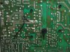
 IMG_1865-top pcb.JPG685.5 KB · Views: 394
 -
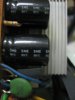
 IMG_1874-secondary caps.JPG846.4 KB · Views: 168
 -
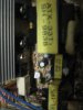
 IMG_1897-back pcb.JPG900.7 KB · Views: 279
 -
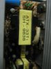
 IMG_1901-main caps.JPG155.1 KB · Views: 127
 -
 IMG_1904-HeatSink1.JPG172.8 KB · Views: 151
 -
 IMG_1907-HeatSink2.JPG172.5 KB · Views: 224
 -
 IMG_1880-desolder secondary caps.JPG188.7 KB · Views: 204
Last edited by a moderator:

")