Maker Pro
Maker Pro

Need Help Analyzing Constant Current Source

alfa88

Dec 1, 2010
349
Joined
Dec 1, 2010
Messages
349
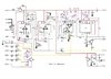
Attached is a schematic of a multimeter section of a SWTP Universal Digital Equipment kit (70s vintage). The circuits in violet are what I suspect are the cause of a malfunction. Fortunately I was able to find a functioning unit and found several discrepancies in the original schematic. The malfunction is that with no input on IN there should be a 1Hz or less pulse on pin C . At least that's my understanding. If I pull IC3 I get an approx. 2Hz pulse. Measuring pin 2 of IC3, IC removed the reading is 0V. IC3 installed the reading on pin2 is approx. 2.4V. I've checked the continuity of Q6-8, D3, D9, D10. I'm awaiting parts to breadboard this section but in the meantime I'm feeling pretty incompetent.
Note: The section in the lower Left(in violet) is, I'm 99% sure, the constant current source for the Ohmmeter function which at the moment doesn't appear to be working.
 

Attachments

  • Electronics Point.jpg
    Electronics Point.jpg
    45.3 KB · Views: 14

Harald Kapp

Moderator
Moderator
Nov 17, 2011
13,719
Joined
Nov 17, 2011
Messages
13,719
Looks like IC 4 is a 555 timer ic in monostable configuration. It should deliver no pulses unless triggered by ic3 via R4.
But I have no clue about the function of the other ics and unfortunately not the time to analyze the circuit.
 

alfa88

Dec 1, 2010
349
Joined
Dec 1, 2010
Messages
349
Looks like IC 4 is a 555 timer ic in monostable configuration. It should deliver no pulses unless triggered by ic3 via R4.
But I have no clue about the function of the other ics and unfortunately not the time to analyze the circuit.
IC1 is a polarity separator and has a transistor stage to drive an LED indicating a negative Voltage. Keep in mind this is a 70's vintage circuit and digital meters were pretty wiz-bang back then. IC2 is a summer. IC3a is an integrator serving as a ramp generator IC3b is a comparator that drives the 555 monostable that outputs to a 7 segment display as well as providing a feedback pulse to the ramp generator. Q5 is for overflow and Q4 provides timing and reset for the counter/display. My issue is with the current source circuitry, Q6-Q8. The current source concept seems simple enough but I can't seem to grasp what Q6 and Q7 are doing and removing IC3 seems to restore the Voltage readings I have taken from a functioning unit. I've tried several replacements for IC3 and tested continuity of Q6-8. BTW, R39 is a sensistor and I substituted it with a PTC thermistor since sensistors seem to be as obsolete as dinosaur eyeballs. I even swapped out the sensistor from the good board just in case and that didn't do it. I'm waiting on an Amazon order for more JRC4558 opamps hoping that maybe I had a bad batch but other than that I'm stuck.
 

Harald Kapp

Moderator
Moderator
Nov 17, 2011
13,719
Joined
Nov 17, 2011
Messages
13,719
I can't seem to grasp what Q6 and Q7 are doing
So hard to see which one is Q6 and which one Q8. Let's assume Q6 is the PNP with the base connected to the zener diode and Q8 is the JFET (just to set up common terms. Swapt Q6/Q8 if I read the diagram incorrectly). I say that Q8 together with the 3.3 kΩresistor between gate and source is a first current source (low accuracy) that drives a pre-regulated current into the zener diode (and a small part into the base of Q6) to keep the zener diode in a well defined operating point. Thus Q6 and its associated emitter resistors will create an even better controlled constant current. The sensistor/PTC is probably designed into the circuit to compensate any remaining temperature dependencies.
Q7 would be used to turn off the above current source by applying +6 V to the base of Q6, setting VBE of Q6 to 0 V. This would be used, I presume, to reset the integrator IC3.

The idea seems to be that the timing of the pulses at the output of IC4 depends on the amplitude of the input voltage. Measuring timing in a digital circuit is comparatively easy and could be used to display a value proportional to the amplitude of the input signal. This is imho a (single) slope ADC.
 

alfa88

Dec 1, 2010
349
Joined
Dec 1, 2010
Messages
349
Ebay Pic.jpg Thank you for your analysis it helps my confusion. Attached is a picture of the thing I'm working on. If I'm not mistaken Don Lancaster helped design the line and some of the information was published in Radio Electronics. There was some sort of falling out and further details of the product line was not available unless you had purchased the kit from the long since defunct SWTPC. The Idea behind it was to have a mainframe that provided the display as well as a timebase for plugins with various functions. The multimeter seemed to be the most ambitious among them. You are correct in that Q8 is the JFET and Q6 is the PNP
 
Last edited:
Top