Hey Boobtube!
Before we start:
Attempting to repair ANY AC MAINS CONNECTED APPLIANCE HAS THE POTENTIAL TO CAUSE:
FIRE
PERSONAL INJURY
DAMAGE TO THE FIXTURE
DAMAGE TO OTHER DEVICES CONNECTED TO THE MAINS
Replacement of components w/o intimate knowledge about the circuit being modified is DANGEROUS.
Proceed accordingly.
A lot depends on what the diode is used for ... the salient features of diodes in general include:
1) Voltage Rating (Vr)
2) Current Rating (iF)
3) Reverse Recovery Time (Trr)
4) Forward Voltage (Vf)
And in your particular case, finding a diode with the same footprint is highly desirable.
For line frequency rectification Trr and Vf are generally not a concern; however, if the diode is part of a high-speed switching circuit then Trr and Vf are very important and intimately linked to Vf, iF and package size (ie footprint).
Schottky Diodes are generally favored for rectification of relatively low voltages at relatively high nominal frequencies (<100V // <250kHz) and are available in relatively high currents.
Silicone didoes tend to dominate line frequency rectification (<500Hz > 85Vac ***It is important to note that nominal grid voltages are RMS voltages ... the actual peak voltage being the RMS Voltage * sqr(2) ... so 120Vac has a peak voltage of 120 * 1.414 = 169.7V .... 240Vac * 1.414 = 339.4V ***. )
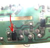
So, how can you tell what this diode does? If the diode is connected directly to either of the AC inputs and then to a relatively large capacitor it is a pretty safe bet it is used for line rectification. If this is the case, then you should look for a diode with a Vr >= 350V if the design input is for 85Vac to 240Vac (typical Vr voltages might be 400V to 600V).
Next you need to determine the maximum current ... Generally this will be printed clearly on the device ... ie:
Max Current = 0.5A
If there is no current rating printed on the device, then you can guesstimate the current based on the rated output .... For example, if the device is rated @ 50W, then use P=iE to calculate the current ... use the MINIMUM voltage rating:
50W = iE --> E= 85Vac -->> 50/85 = 0.6A
There is a large selection of 1A diodes in the 350V-1000V range. One example is the SM4005 which is available in a footprint that looks similar to the one pictured. The SM4005 is rated for line frequency rectification (50Hz/60Hz) 600V, 1A.
WARNING ****The SM4005 is COMPLETELY UNSUITABLE for rectification of high frequency voltages like those found in the output stage of a forward converter.*****
IF the diode in question is NOT connected directly to one of the AC inputs then you will need a LOT MORE INFORMATION prior to selecting a replacement. The first step is to determine the nominal current of the LEDs ...
Typical light fixtures connect LEDs in a combination of series & parallel to achieve a "reasonable" Forward Voltage and Current. Typical White LEDs have a forward voltage (Vf) of 3.0V to 3.8V and are designed for currents from 15mA to 1A, with the most common current ratings being 50mA to 300mA each. So, to achieve a 12W output using 100mA rated LEDs (@ 75mA) with a nominal forward voltage of 3.4V:
P = iE --> 75mA * 3.4V = 0.255W each
12W/0.255W = 47 LEDs ... Round up to 48
Configuring the LEDs is the type of engineering that mixes art, physics and pessimism ... (and, in case you were unaware, Engineering, by definition ALWAYS includes **cost** as a primary directive) ... On the one hand, a single string of 48 LEDs in series has a fair number of advantages with respect to cost and efficiency; however, if a single LED fails then the light fails. Additionally the 163V requisite (48 * 3.4V = 163.2) would need to be regulated @75mA which is a bit tricky. At the other extreme there is 48 LEDs in parallel ... the problem here is regulating 3.6A @ 3.4V ... this requires a large inductor (ie: Large - Expensive) and even then requires very high switching speeds (which increases the cost of the Switch and the diodes) ...
So a reasonable compromise would might be to have four LEDs in series with 12 of these series in parallel ... a typical diode array would look like this:

Nominal Voltage would be 4 * 3.4V = 13.6V, and nominal current would be 0.075 * 12 = 0.9A (900mA). With 12 in parallel if a single LED dies it will only affect one series connected set of 4 LEDs. The driver will still output 900mA, and the remaining 11 series will share this current --> 900mA/11 = 81.8mA per series ... still below the nominal maximum rating of 100mA/LED.
****************************************************************************************************************
****************************************************************************************************************
Side Note:
The LED arrays I build inner-connect the series so that the 12 LEDs in any given position are all connected in parallel at both the anode and the cathode like this:

When configured in this way the failure of any given LED only increases the current in the remaining LEDs in that particular column, and the other 47 LEDs remain active. Additionally variations in individual LED Forward Voltage and variations in Forward Voltage associated with un-even heat sinking are minimized. I have not yet encountered a commercially designed LED bulb that employs this technique, most likely because it increases the complexity of the connections considerably; however, the improvements in reliability AND performance are considerable.
End Side Note
****************************************************************************************************************
****************************************************************************************************************
Soooo ... You should be able to use a VOM (Volt-Ohm Meter or "Multimeter") to determine the series/parallel connections of the LEDs ... (I will assume you have enough technical knowledge to achieve this task w/o instructions? If not, then you really Should Not consider yourself qualified to attempt to repair this light, consider the $50 price tag an investment in safety.)
Once you know the configuration of the LEDs it should be fairly straight-forward to calculate the requisite voltage and current of the diode in question. To be honest, assuming it is this diode that failed, **AND** is the only actual problem with your light, I would go with the fastest Trr, iF = 2+ amp, Vr = 40V+ schottky diode I could find in a footprint that will fit on the PCB.
****************************************************************************************************************
****************************************************************************************************************
Side Note:
"LED Chips" are simply an array of smaller LEDs bonded to a common heat sink and factory connected in series/parallel to approach some nominal Voltage and Current (Example: the most common 10W LED chips are configured to have a nominal maximum Vf of ~12V and a nominal maximum current of 800mA (0.8 * 12 = 9.6W .... Attempting to actually drive a 10W LED chip @ 10W would lead to very premature failure of the chip even with a huge heat sink ... point being LEDs, like many other semiconductors are generally rated well beyond their sustainable continuous capabilities ... in most cases the light fixtures I build I design the current to be 10% to 25% of nominal maximum rating ... ie, I typically drive the 10W LED chips @ 75mA to 150mA each ... I have fixtures that have been on continuously for over 5 years <<45000 hours>> with zero failures ... I do have one fixture where I run the 10W chips @ 300mA ... I typically have to replace one or two of the chips every year ... it uses 16 chips ~50W).
End Side Note
****************************************************************************************************************
****************************************************************************************************************
Two final thoughts ...
The "flickering" you describe is typical of an LED going bad rather than a problem with the driver. Typically if an active component fails in a driver, the driver fails completely. Not 100% of the time. If the diode is part of the primary rectifier connected to the AC Mains, it is certainly possible the circuit might still work while causing the described "flickering", but I would bet against that being the case.
Many of the LED drivers used in mass-market LED fixtures are available on ebay. Certainly NOT all, but a surprising number of LED bulbs & fixtures I have disassembled contain Drivers I have purchased from ebay. Notable exceptions are the Cree bulbs & fixtures ... I have never encountered any of those drivers on ebay. Even if you can't find an exact match, once you know the Nominal Voltage and current, it is likely (if there is room) you could replace the entire driver.
Good Luck!
Fish