Maker Pro
Maker Pro

Mysterious diode identification help!

wdoug72

Jul 28, 2012
21
Joined
Jul 28, 2012
Messages
21
Hey everybody my name is Will and this is my first post on the forum. I have an older (circa 1970s) branson b52 ultrasonic cleaner and in need to replace two of the 4 power diodes. The problem is that I cannot figure out what I need to replace them with. They are solid black with just one blue band on them. I have attached a file to show exactly the components I'm talking about. Thanks in advance for all your help.
 

Attachments

  • Bransonb52 power diode.jpg
    Bransonb52 power diode.jpg
    146.6 KB · Views: 1,211

markm6164

Jan 22, 2012
118
Joined
Jan 22, 2012
Messages
118
They look like rectifier diodes. Do you have any more power specs of the unit? Something like 1N4004 are 400v 1A. Depends on the unit specs though.
 
Last edited:

Mitchekj

Jan 24, 2010
288
Joined
Jan 24, 2010
Messages
288
Definitely a bridge rectifier, the X and Y caps are pretty obvious. I'd agree w/ Mark that the 4000 series diodes would be the first guess, though to be sure the 5400 series (1N5404) may be better replacements as they are 3A devices since we are unsure of the current draw.

I would be very surprised if replacing them brought the unit back to life though. That kind of damage screams "other components downstream are bad" at me. I'm thinking shorted FET or similar.
 

(*steve*)

¡sǝpodᴉʇuɐ ǝɥʇ ɹɐǝɥd
Moderator
Jan 21, 2010
25,510
Joined
Jan 21, 2010
Messages
25,510
Yeah, the look like rectifier diodes. The giveaway is that there are 4 of them together.

Is the stripe on the one that has half the epoxy remaining at the opposite end to the ones that are intact?

And out of curiosity, did you find them like this, or did you break off the epoxy to see what was inside? (not that it matters)

The important thing is to find he voltage and current so a suitable replacement can be found.

If they can physically fit, something rated at 400V and 4A should well and truly work. However the leads may not fit through the holes.

If you can find a part number on the existing parts (as mentioned above) then we can be totally sure :)
 

wdoug72

Jul 28, 2012
21
Joined
Jul 28, 2012
Messages
21
Thanks everyone so much for your help! I attached another picture of the tag on the side of the unit that gives you the idea of the specs of the unit. Unfortunately the two rectifiers that are intact do not seem to have any part numbers on them. This at one time was a perfectly good working unit but one night I left it running for too long and destroyed the transducers. I picked up some new ones and attempted to wire up an in wall countdown timer into the unit so this wouldn't happen again. So i plugged her in and tried her out, but must of wired her wrong as I fried those power rectifiers and the fuse. Ill also attach a picture of the complete driver board.
 

Attachments

  • 0730021922.jpg
    0730021922.jpg
    145 KB · Views: 1,006
  • 0730021905.jpg
    0730021905.jpg
    129.7 KB · Views: 904

(*steve*)

¡sǝpodᴉʇuɐ ǝɥʇ ɹɐǝɥd
Moderator
Jan 21, 2010
25,510
Joined
Jan 21, 2010
Messages
25,510
I would probably replace them with 400V 4A diodes. These are polarised components. Make sure you replace them with the stripes on the correct ends. In a bridge rectifier, two are connected one way, and two the other (typically). You can check by seeing which end the stripe is on the diode that has half its body left.

Next trick is to connect up the power without the transducers and see if any smoke comes out.

If it doesn't, try connecting the transducers.

It's possible that you have damaged more than the rectifiers. If so, you'll probably blow the fuse -- and possibly a rectifier or two -- when you turn on the power (or when you connect the transducer).

If this is the case, you'll need to do more trouble shooting.

An image of the other side of the board would be useful if you need more assistance.

Also, is this connected to the mains, or is there a transformer that you have not shown us? If so, do you know the secondary voltage?
 

wdoug72

Jul 28, 2012
21
Joined
Jul 28, 2012
Messages
21
Does anyone have a part number for these 4a 400v barrel diodes? The driver board is actually hooked up directly to the mains. The only other thing that gets hooked up to the board is the inductor for the transducers. Ill post another picture of the backside of the board when I get home.
 

davenn

Moderator
Sep 5, 2009
14,264
Joined
Sep 5, 2009
Messages
14,264
Does anyone have a part number for these 4a 400v barrel diodes? The driver board is actually hooked up directly to the mains. The only other thing that gets hooked up to the board is the inductor for the transducers. Ill post another picture of the backside of the board when I get home.

1N5404 ... if you really wanna use 4A ones.
but its really a serious overkill. The ones in there look to be the equiv of the standard 1A 1N4004 series

Dave
 

wdoug72

Jul 28, 2012
21
Joined
Jul 28, 2012
Messages
21
If you guys think 1A should suffice then Ill just go with those. Here is a a picture of the bottom of the unit.
 

Attachments

  • b52.jpg
    b52.jpg
    145.7 KB · Views: 694

(*steve*)

¡sǝpodᴉʇuɐ ǝɥʇ ɹɐǝɥd
Moderator
Jan 21, 2010
25,510
Joined
Jan 21, 2010
Messages
25,510
If you guys think 1A should suffice then Ill just go with those. Here is a a picture of the bottom of the unit.

Maybe. We don't really know what voltage or current that circuit runs at.

Doesn't appear to be mains voltage, and the traces are narrow enough that it's probably not super high current.

So we're really just speculating. My position is one the very conservative end of the spectrum.
 

wdoug72

Jul 28, 2012
21
Joined
Jul 28, 2012
Messages
21
Heres an update,

I replaced the power rectifiers with 1N5404 type which had for a previous project and have also replaced the blown out fuse (rated 250V 5A) with a replaceable AGC/3AG type holder. I have powered on the unit with no transducers attached and get a small audible hum from the transistors, but when I attach the transducers to the circuit it blows the fuse. Any thoughts? Could there be a problem with the transistors when a full load is applied?
 

(*steve*)

¡sǝpodᴉʇuɐ ǝɥʇ ɹɐǝɥd
Moderator
Jan 21, 2010
25,510
Joined
Jan 21, 2010
Messages
25,510
get a small audible hum from the transistors

I can't see that being a good thing.

I'd almost bet that one of them is shorted.

How much current is drawn (at what voltage) when no transducer is attached?

Does anything get warm or hot (check the transistors especially)
 

wdoug72

Jul 28, 2012
21
Joined
Jul 28, 2012
Messages
21
Voltage from the RF+ and RF- leads (where the transducers are hooked up) reads around 50V. The transistor circled in the attached photo gets very hot when running so I assume this one is bad. Is it possible to locate a replacement and would it be in my best interest to replace all 4?
 

(*steve*)

¡sǝpodᴉʇuɐ ǝɥʇ ɹɐǝɥd
Moderator
Jan 21, 2010
25,510
Joined
Jan 21, 2010
Messages
25,510
The one that gets very hot may be the one that's OK.

I'd probably replace them all, given that there's likely a faulty one and others may have been damaged.

I can't read the markings on them, can you tell me what they are, and are they all the same?

See if there's a short between the case and either of the 2 leads. (The case is the collector, the 2 leads are base and emitter)
 

wdoug72

Jul 28, 2012
21
Joined
Jul 28, 2012
Messages
21
There are two different types of transistors and they all have just numbers on them no company names or logos. The two on the left are labeled 466 458-056 7805 and the two on the right are labeled 466 458-056 7812.
 

KrisBlueNZ

Sadly passed away in 2015
Nov 28, 2011
8,393
Joined
Nov 28, 2011
Messages
8,393
Have you made any progress on this?

I found an old thread on another site that mentions the 458-056 transistor:
http://www.candlepowerforums.com/vb/showthread.php?22438-Ultrasonic-Cleaner-power-supply-HELP!

Someone in that thread also mentioned that you should never run these power supplies with no transducer connected. That may not apply to your power supply; I couldn't say.

It seems to be an International Rectifier part. Presumably the 7805 and 7812 markings are the date codes, so the chance of either of them being available now is roughly zero.

I found it mentioned on one site, which mentioned a replacement: the NTE53. This is a high-voltage, high-speed silicon NPN transistor in a TO-3 package, so it certainly could be a suitable replacement.

I would be interested to see a schematic of the board. Can you trace it out? Otherwise, can you annotate your top side photo with all the visible markings on all the components, and I'll trace it out myself. There isn't much to it.

The four power resistors (grey rectangular things at the ends of the heatsinks) are mounted upside down so you probably can't see the markings; you could lift one temporarily (they're probably all the same) or measure them with a multimeter on ohms range. And all the blue capacitors have markings on the side that aren't visible in the photo; could you annotate a photo and add the markings on it? Also I would need to know what connects to the three connectors on the left side. They're marked +RF, -RF and COIL on the copper side of the PCB.

With a board of that age, many of the components have probably deteriorated. The carbon resistors (large cylindrical things with colour bands) would be a prime suspect, as well as all the semiconductors (transistors and diodes). Those resistors appear to be brown-green-orange which is 15 kilohms. You'll probably have to lift one end out of circuit. But I think it would be worth measuring them.

I'm happy to try to help if you're serious about fixing this board.
 

wdoug72

Jul 28, 2012
21
Joined
Jul 28, 2012
Messages
21
Well I'm not really well versed in circuit tracing so I enclosed a photo and annoted the top side with all visible markings. I also labeled everything connected to the RF+ RF- and COIL terminals. The large 15 kilohm resistors measured 14.62 and 14.64 kilohms on my multimeter. I'm very interested in getting this board fixed and any help would be appreciated.
 

Attachments

  • 0730021922 - Copy.jpg
    0730021922 - Copy.jpg
    139.3 KB · Views: 1,158

KrisBlueNZ

Sadly passed away in 2015
Nov 28, 2011
8,393
Joined
Nov 28, 2011
Messages
8,393
That photo is excellent, nice work.

I've nearly finished drawing out the schematic but I have a few questions.

1. What is the rating of the fuse? Is it the 5A/250V one that you replaced? Does it have any other markings like a letter T (meaning "time delay")? What does the wire look like inside? Have you still got the blown one to look at?

2. Can you check the markings on the four smaller blue capacitors that you marked as "3" on your annotated diagram (three side-by-side and one near the bridge diodes). Two of them look bigger than the other two. Please check all four.

3. For each of the diodes (four in the bridge rectifier, and two strings of three near the heatsinks), which side has the blue stripe (cathode)? I THINK I know, but I'd like to be sure.

4. Does the small coil next to the oscillator transformer have anything inside it (apart from the paper tube)?

5. The oscillator transformer (middle of the board, with white goop around it) is a custom made part. I would need the details of it to draw the diagram fully, but it's hard to tell with just a multimeter (even if you remove it from the board). All you can do is measure continuity between each different pair of wires to find what connects to what internally, then measure resistance between pairs of wires that had continuity. That MIGHT tell me enough to draw it correctly. I think there are two separate windings, one on each side, and the side that doesn't have two wires shorted together on the PCB has a tapped winding.
If you want to measure the transformer out-of-circuit, solder-suck the holes and free up the wires before you take it out. Remember which way round it goes!
It's not essential to have this information; it will just make my schematic more complete.
 
Last edited:

wdoug72

Jul 28, 2012
21
Joined
Jul 28, 2012
Messages
21
1. It is the same 5A/250V I replaced. I assume it was a fast burn but that may not be the case. The only markings on it say LITTEL FUSE USA. I enclosed a picture of the blown fuse.

2. Double checked and they all seemed to be labeled the same.

3. The four in the bridge rectifier the stripes are on the side closest to the edge of the pcb. The two strings of three have the blue stripes on the component side closest to the COIL RF+ and RF- terminals. ( I hope this helps)

4. Seems to be filled with plastic.

5. I will hopefully be able to do this tomorrow

I hope this helps! Thanks
 

Attachments

  • fuse.jpg
    fuse.jpg
    94.6 KB · Views: 663

KrisBlueNZ

Sadly passed away in 2015
Nov 28, 2011
8,393
Joined
Nov 28, 2011
Messages
8,393
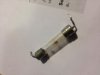
OK Will, thanks for the responses. Here is the schematic, which I think is complete apart from the details of T1, and a photo of both sides of the board with component references that match those I assigned on the schematic.

attachment.php


attachment.php


Without the details of T1 I can't be too sure how the circuit works, but it's clearly an oscillator with a push-pull output, using two transistors on each side.

The humming noise you mentioned is probably quite normal. The whole circuit operates from bridge-rectified mains, with only 3 uF of smoothing, so its output voltage varies with the bridge-rectified mains voltage, which is at 120 Hz (assuming 60 Hz mains).

If one transistor is getting hot and the others aren't, I would suspect that transistor. Personally I would replace all four, unless they are prohibitively expensive. You're unlikely to do any damage by replacing just one, but the circuit may work better if they're all the same.

As I said, I think the NTE53 is probably the most suitable replacement. Most TO-3 transistors are not suitable.

I'd be happy to update the schematic with details of T1 if you are prepared to measure it.

Edit: Regarding replacement transistors. I should have said that (a) each pair of transistors (on the same heatsink) should be the same type, otherwise they won't current-share properly, and (b) you may have trouble finding a suitable replacement - power switching of this type is almost exclusively done with MOSFETs now, and has been for over a decade.

Digikey doesn't have ANYTHING suitable; Mouser does, but only three types in the TO-3 (metal can) package. These are BUX48, BUX48A, and 2N6547, all from STMicroelectronics and all around USD 6 each. Personally I would replace all four with 2N6547s from Mouser.
 

Attachments

  • epoint wdoug72 ultrasonic cleaner driver board both sides with component references.jpg
    epoint wdoug72 ultrasonic cleaner driver board both sides with component references.jpg
    78.7 KB · Views: 5,667
  • epoint wdoug72 ultrasonic cleaner driver board schematic.gif
    epoint wdoug72 ultrasonic cleaner driver board schematic.gif
    13.9 KB · Views: 9,572
Last edited:
Top