Oh, OK, so you want the soft start to happen again after a brief power outage (which presumably it's not doing).
View attachment 14607
Try this. I'll have to figure out component values later, but here is what it does. Tell me if you think it's right.
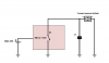
Rx and Cx stand in place of your soft start capacitor and current source.
When the power is on and the input voltage exceeds Vz (D1) by some margin, Q1 is turned on pulling the gate of Q2 low, turning it off (and allowing Cx to charge).
When the input voltage falls below Vz, Q1 turns off, allowing Q2 to turn on, shorting the capacitor Cx.
In more detail...
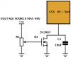
As the input voltage starts to drop, the voltage across R1 drops. This causes the current through D1 to fall. Eventually there is insufficient current to maintain both 0.7V across R2 and excess for the base current of Q1. At this point Q1 begins to turn off. This allows the gate of Q2 to be pulled high. If the input voltage falls very fast, C1 contains enough charge to turn on Q2 (which need not be a logic level mosfet). In this case, D2 prevents C1 from discharging prematurely.
Note that because the input voltage can exceed Vgs(max), which is typically around 20V, the zener diode D3 between the gate and source of Q2 exists to clamp the gate voltage well under Vgs(max), but well above what is required to turn the mosfet on sufficiently.
As the voltage rises from zero, Q1's base is held to the emitter voltage keeping it turned off. This will allow the voltage at the gate to rise. If C1 was discharged, this will begin to charge C1 and at about 5V the mosfet will be substantially turned on. (if C1 was still at or above 5V, the mosfet would already be on. So the soft start capacitor is still held at 0V. As the input voltage rises above Vz (D1) a current starts to flow through D1. This causes a voltage drop across R1. When the input voltage is sufficient that the voltage drop across R2 reaches about 0.65V (see the equation below) the Base-emitter junction of Q1 becomes forward biased and any additional current flows through the base of the transistor. This allows the transistor to turn on. As the voltage rises further, more and more current flows through the base until at Vcc of 40V, the base current is close to 2mA.
R1 - 10k
R2 - 5k6
R3 - 39k
C1 - 4.7uF 63V
D1 - 9V1 Zener
D2 - 1N4148
D3 - 9V1 zener
Q1 - BC548
Q2 -
2N7002 (note that Vgs of 5V is plenty to turn this on)
With the component values shown, the device will switch in the region of 10V to 11V.
Q2 will be turned off when the voltage drop across R2 (Vbe) reaches about 0.65V to 0.7V This is about Vbe + Vz + (R1/R2)*Vbe. For the component values chosen it will be calculate as close to 11V. However it is important to note that the zener voltage will be a little low at low currents, so the switching point may be lower.
At 40V, the current drawn will be: (40 - 9.1)/15600 + (40 - 0.6)/22000 = 0.002 + 0.001 = 0.003 A = 3 mA
Note that the mosfet may remain turned on for a substantial time after power is removed as it is limited (mostly) by leakage through Q1 and D3 and the self discharge of the capacitor. As soon as the input voltage hits about 10V, the mosfet will be turned off again
If you're lucky the datasheet for whatever zener you choose will give you V vs I curves. As used here, R2 means that you're interested in Vz at about 100uA. Note that in addition to Vz varying with current, zener diodes have a significantly wide tolerance, the actual zener voltage (even at a higher current) can vary +/- 5% (although you rarely see this amount of variation in practice).
 Enter to Win a Raspberry Pi 4 built into a compact keyboard! We'll be selecting the winner at the end of this month - click here for more information.
")