Hello,
This is my first post on Electronics Point, and I am by no means a circuit guru, so please bear with me if I seem to make rookie mistakes in my posts") .
.
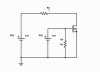
I am having trouble using an n-channel enhancement-type MOSFET (part no. is NTE2996) to use one voltage source (PS1) to switch current coming from an external power supply (PS2) on and off. I have attached a diagram of the circuit that I have been testing so far, which I will make references to from now on.
Before I explain the problem, a bit of context might be helpful. The circuit that I am trying to switch is for a 3D printer's heated bed. The printer's old heated bed was inadequate, and I am trying to install a new one, but the current that the new one draws is too much to run through the 3D printer's circuit board directly, hence the MOSFET. Also, the power supply that the 3D printer runs off of is inadequate to supply the current needed for the new heated bed, so that is why there are two power supplies in my diagram.
PS1 in the diagram really refers to the two leads on the 3D printer's circuit board that were being used to heat the old heated bed, so the circuit is a bit more complicated than my diagram shows it to be, since "PS1" is not directly connected to the actual power supply that the printer is using. I can usually control the voltage coming out of PS1 via software, and that is how I am switching the MOSFET.
Okay, now for the problem. When I disconnect PS2 and replace it with the leads of an ohmmeter, the circuit works as it should. When I use the printer software to turn off PS1, the gate-source voltage is 0V, and the drain-source resistance (measured on the ohmmeter) is extremely high. When I use the printer software to turn on PS1, the gate-source voltage is 12V, and the drain-source resistance is around 1 ohm, as it should be.
When I connect PS2 in lieu of the ohmmeter, however, the circuit does not work as it should. Even though I do not have PS1 turned on via the printer software, the gate-source voltage reads 12V, and the printer's heated bed (R2) heats up on its own. I am not sure if the current from PS2 is leaking through from the drain to the gate, or if it is somehow causing PS1 to turn on when it is not supposed to.
When I removed the MOSFET from the circuit, the resistance between the drain and the gate read as infinite with the positive lead on the drain and the negative lead on the gate, which is as it should be (the two are physically isolated within the MOSFET, aren't they?). Oddly, when I connect the ohmmeter the other way with the MOSFET disconnected (plus on the gate and minus on the drain), the drain-source resistance becomes very low. I have some theories for why this happens, but I am not entirely sure of them. I also don't know exactly how the 3D printer circuit board switches PS1, except that it is also done using a MOSFET, so it is hard to tell what is causing the gate-source voltage to measure 12V when I am not telling PS1 to turn on.
Could I please have some help solving this problem?
Thanks for reading my rambling post!
- mrShrimp
This is my first post on Electronics Point, and I am by no means a circuit guru, so please bear with me if I seem to make rookie mistakes in my posts
.I am having trouble using an n-channel enhancement-type MOSFET (part no. is NTE2996) to use one voltage source (PS1) to switch current coming from an external power supply (PS2) on and off. I have attached a diagram of the circuit that I have been testing so far, which I will make references to from now on.
Before I explain the problem, a bit of context might be helpful. The circuit that I am trying to switch is for a 3D printer's heated bed. The printer's old heated bed was inadequate, and I am trying to install a new one, but the current that the new one draws is too much to run through the 3D printer's circuit board directly, hence the MOSFET. Also, the power supply that the 3D printer runs off of is inadequate to supply the current needed for the new heated bed, so that is why there are two power supplies in my diagram.
PS1 in the diagram really refers to the two leads on the 3D printer's circuit board that were being used to heat the old heated bed, so the circuit is a bit more complicated than my diagram shows it to be, since "PS1" is not directly connected to the actual power supply that the printer is using. I can usually control the voltage coming out of PS1 via software, and that is how I am switching the MOSFET.
Okay, now for the problem. When I disconnect PS2 and replace it with the leads of an ohmmeter, the circuit works as it should. When I use the printer software to turn off PS1, the gate-source voltage is 0V, and the drain-source resistance (measured on the ohmmeter) is extremely high. When I use the printer software to turn on PS1, the gate-source voltage is 12V, and the drain-source resistance is around 1 ohm, as it should be.
When I connect PS2 in lieu of the ohmmeter, however, the circuit does not work as it should. Even though I do not have PS1 turned on via the printer software, the gate-source voltage reads 12V, and the printer's heated bed (R2) heats up on its own. I am not sure if the current from PS2 is leaking through from the drain to the gate, or if it is somehow causing PS1 to turn on when it is not supposed to.
When I removed the MOSFET from the circuit, the resistance between the drain and the gate read as infinite with the positive lead on the drain and the negative lead on the gate, which is as it should be (the two are physically isolated within the MOSFET, aren't they?). Oddly, when I connect the ohmmeter the other way with the MOSFET disconnected (plus on the gate and minus on the drain), the drain-source resistance becomes very low. I have some theories for why this happens, but I am not entirely sure of them. I also don't know exactly how the 3D printer circuit board switches PS1, except that it is also done using a MOSFET, so it is hard to tell what is causing the gate-source voltage to measure 12V when I am not telling PS1 to turn on.
Could I please have some help solving this problem?
Thanks for reading my rambling post!
- mrShrimp