Maker Pro
Maker Pro

MOSFET I don't understand you!

bibiz999

Feb 2, 2011
43
Joined
Feb 2, 2011
Messages
43
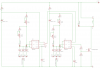
I connect 12V+ to the Drain and the Source to Ground of a MTM24N45E 400V 24A N-Channel TMOS E-FET with nothing connected to the Gate.
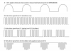
How come I measure a 4V+ half sin wave at the Drain, and enough current to brightly light a LED?
I though MOSFET didn't conduct when the gate is not fed anything. I've tried it with a IRFC50 600V 11A N-Channel HEXFET Power MOSFET (and a 2SK1016) but it's the same.

Thanks in advance,
 

(*steve*)

¡sǝpodᴉʇuɐ ǝɥʇ ɹɐǝɥd
Moderator
Jan 21, 2010
25,510
Joined
Jan 21, 2010
Messages
25,510
There are several reasons.

Firstly, you may have touched the mosfet with something that held enough charge to slightly turn the mosfet on.

Secondly, the mosfet may be a depletion mode device that is normally on and requires a gate voltage to turn off.

Thirdly, the device may be damaged and is conducting slightly.

In general, you should NEVER leave the gate open. For most mosfets, a fairly large resistor (say 100k) connected from gate to source will keep it behaving itself when gate drive is removed.

As an adviceful viceroy I advise (even if your device were a vicenary of unserviceable navicella with crevices caused by a avicennia) you would be viceless, and we would be doing a disservice, not to offer you advice.
 

bibiz999

Feb 2, 2011
43
Joined
Feb 2, 2011
Messages
43
Yep, a R 100K between Gate - Source stoped the current flow (not voltage fluctuation though) when nothing is driving the Gate.

This is a unconvenient behavior since I'd thought the MOSFET would follow the gate driver pulse (dual astable 555) but it does not! I makes this half sin wave on it's own behind the driver pulse!
Should I leave the 100K R between Gate-Source to prevent it from doing it when the driver is low?

Thank in advance!
 

(*steve*)

¡sǝpodᴉʇuɐ ǝɥʇ ɹɐǝɥd
Moderator
Jan 21, 2010
25,510
Joined
Jan 21, 2010
Messages
25,510
Yes, leave the resistor between gate and source. It will ensure that the device stays off when power is removed.

As for the other behaviour, I think it's time for you to show us a circuit diagram and perhaps some of what you're seeing on a scope (I presume that's where you see sine waves)
 

bibiz999

Feb 2, 2011
43
Joined
Feb 2, 2011
Messages
43
Yes, leave the resistor between gate and source. It will ensure that the device stays off when power is removed.

As for the other behaviour, I think it's time for you to show us a circuit diagram and perhaps some of what you're seeing on a scope (I presume that's where you see sine waves)

Yeah sure her it is!

The cct control pulse frequency (signal B) with optional gating (signal C) as shown in the signal form file attached.

Signal A shows what happend when Gate is left open. Signal D shows what happend when Gate is fed with signal B ???

When Signal C is apply to Gate, signal A is intertwine with signal D. A 100K resistor doesn't change the form of the signal (it might change the current level but it doesn't show on the scope).

Seems strange to me but again, I'm a newbie so...

Thanks for your help in advance...
 

Attachments

  • signal form.png
    signal form.png
    63.1 KB · Views: 224
  • Frequency generator.png
    Frequency generator.png
    30.4 KB · Views: 322

(*steve*)

¡sǝpodᴉʇuɐ ǝɥʇ ɹɐǝɥd
Moderator
Jan 21, 2010
25,510
Joined
Jan 21, 2010
Messages
25,510
I would make R7 about 10R and R8 around 10k.

As far as I can tell R8 only serves to keep the mosfet off when power is removed. Is that right?

It may also be interesting to have a look at Vcc for the 555's.

What is the load?

On that 4th trace, are the bottoms of the waveforms really horizontal, or are they sloped?
 

bibiz999

Feb 2, 2011
43
Joined
Feb 2, 2011
Messages
43
I would make R7 about 10R and R8 around 10k.

As far as I can tell R8 only serves to keep the mosfet off when power is removed. Is that right?

It may also be interesting to have a look at Vcc for the 555's.

What is the load?

On that 4th trace, are the bottoms of the waveforms really horizontal, or are they sloped?

Well, isn't the voltage fed to Q1's Gate also divided between R7 and R8?

The load is simply the scope for now!

As for the 4th trace check it out here (pretty strange if you ask me):

http://www.youtube.com/watch?feature=player_profilepage&v=VGOjCkNKreQ

Thanks again,
 

(*steve*)

¡sǝpodᴉʇuɐ ǝɥʇ ɹɐǝɥd
Moderator
Jan 21, 2010
25,510
Joined
Jan 21, 2010
Messages
25,510
Show us the Vcc for the 555s and the +12V while this is all happening.

the voltage applied to the gate is divided between R7 and R8 but you must remember that it has quite a low impedance at high frequencies (due to the gate capacitance) thus the voltage divider can get loaded down.

The only reason for these resistors *might* be if the Vgs(max) is less than 12V.

It looks like the device is probably an IRFPC50 is that right? It has a Vgs(max) of 20V, so no reason for a voltage divider. The gate capacitance is pretty high, so I'd want to see a low resistance between the output of the 555 and the gate of the mosfet. A resistance designed to keep the current below the max 555's output current (around 200mA) would be appropriate.
 

bibiz999

Feb 2, 2011
43
Joined
Feb 2, 2011
Messages
43
Show us the Vcc for the 555s and the +12V while this is all happening.

the voltage applied to the gate is divided between R7 and R8 but you must remember that it has quite a low impedance at high frequencies (due to the gate capacitance) thus the voltage divider can get loaded down.

The only reason for these resistors *might* be if the Vgs(max) is less than 12V.

It looks like the device is probably an IRFPC50 is that right? It has a Vgs(max) of 20V, so no reason for a voltage divider. The gate capacitance is pretty high, so I'd want to see a low resistance between the output of the 555 and the gate of the mosfet. A resistance designed to keep the current below the max 555's output current (around 200mA) would be appropriate.

What do you want to see exactly? Both Vcc are stable on the scope (at 11V and 10.5V for IC1 and IC2) so there is nothing to show. I've connect 3 LED as a load and it change nothing on the Vcc. What do you want to see about 12V+.

The device is a MTM24N45E but the IRFC50 seems to display the same wave pattern and they both have a Vgs (max) of 20V Do you suggest to replace R7 R8 by say, a 10 R?

Again, do you believe I'm right when I expect the output to follow the pulse driver or is this just me?

Thanks...
 

bibiz999

Feb 2, 2011
43
Joined
Feb 2, 2011
Messages
43
Ok, before I change 1 component of the current cct I need a simple answer to an honest question.
Am I right to expect the output of Q1 to follow the pulse driver or is this just me?
If the answer is YES I'll make sure the cct does it! Otherwise I mean...

Bye ciao!
 

(*steve*)

¡sǝpodᴉʇuɐ ǝɥʇ ɹɐǝɥd
Moderator
Jan 21, 2010
25,510
Joined
Jan 21, 2010
Messages
25,510
Am I right to expect the output of Q1 to follow the pulse driver or is this just me?

A lot depends on the load you're driving.

If Vgs is low, the mosfet acts more like a constant current source than a resistor.

If you were driving a motor, for example, then you might find that the voltage across the mosfet would vary.
 
Top