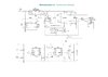
What is not clear to you in the scheme, written in Russian?

See items in red.
And what else motivation can there be? The possibility of using a milliOhm meter is quite limited. Besides resistors of a certain range, there is nothing more to measure.
There's heaps of stuff.
- You could point out the kelvin measuring technique (and possibly even the construction of the probes)
- The circuit appears to have rechargeable lithium batteries with charge management. This alone would be interesting. How does it work?
- The schematic doesn't show the display. Where do we get one? What can you tell us about it?
- It looks like the ICL7660 is always connected to the batteries -- what is the implication of this?
- This circuit can do stuff a multimeter can't (it's worth mentioning this)
- What are some examples of what you can do with it (measuring cable resistance, finding short circuits on PCBs, etc.)
I've been thinking a lot about the stuff you're posting. I think you're trying to do something useful, but I think your posts could be far more useful.
My motivation is very simple. Show people an interesting scheme.
Yeah, that's what I've figured. Just as a head's up, your first post in this forum was very spam-like and that is what got my attention (and held it whilst I confirmed you were not). People spam this site with their own project and a link back to their site all the time. All they do is get links to their site, the posts here are not useful for our members.
Our members can google. If any of them wanted a capacitance meter or a milliohm meter they could just search the internet. To be more useful than a google search you need to add some information which does some amount of critical analysis which goes beyond what might be easily available from reading the original source.
One option is for you to start a thread named something like "Test equipment you can build" and post
all of these projects to it. It might be helpful and useful to others if you post
one post per project with all the information, including:
- The source of the project (i.e. links to it)
- Schematics and images
- Some description of what the project achieves, why one might want one, and the benefits of this project over other options
- Personal experience (if you have any)
- Synopsis of the principals of operation of the circuit.
- Translations of anything not in English.
- Improvements that have been made to the circuit (perhaps by others)
- Comparison between this circuit and alternative methods (e.g. multimeters, etc.)
Another option is to find projects with non-English (Russian?) documentation that may be of interest to people without the ability to easily translate and/or understand the circuit. In addition to the factors listed above, you could include:
- "Western" equivalents of components.
- Re-drawn or annotated schematics with English markup.