Maker Pro
Maker Pro

MIC4609 Mosfet Driver Current spike on Enable

Lord_grezington

May 3, 2013
124
Joined
May 3, 2013
Messages
124
Hello Everyone

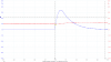
I am trouble shooting one of my PCB's that uses the microchip MIC4609 mosfet driver (I have attached the datasheet). I have it running the motor without any problems but everytime I enable the driver via the EN pin I get a massive current spike that can some times be up to 38A. The Spike only occurs when the enable is driver, if the enable stays on I can adjust the PWM duty 0-90% rapidly without it happening again. This even happens if I have the PWM at 0% and then enable the pin when there is no motor attached... (see trace below-Blue is PSU current and Red is Phase output - High side source)

upload_2018-9-25_15-5-14.png

I tend to think it must be the bootstrap caps, but they are only 0.1uF each, doees not make sense... Below is part of the schematic used (R38 is not fitted and R37 takes ISNS to GND as I had problems with noise in the early days).


upload_2018-9-25_14-59-17.png

Any Idea's?

Thanks
 

Attachments

  • MIC4609.pdf
    833.5 KB · Views: 18
  • upload_2018-9-25_15-3-55.png
    upload_2018-9-25_15-3-55.png
    21.3 KB · Views: 22

(*steve*)

¡sǝpodᴉʇuɐ ǝɥʇ ɹɐǝɥd
Moderator
Jan 21, 2010
25,510
Joined
Jan 21, 2010
Messages
25,510
Where and how are you measuring that current?

Your images are a bit small to allow me to read them.
 

Lord_grezington

May 3, 2013
124
Joined
May 3, 2013
Messages
124
Hi Steve

In this case I have a 0.02OHM power resistor between the PSU and GND input. The GND clip for the scope is closest to the PSU and the probe is closest to the GND input.

I have tried making them larger
upload_2018-9-25_15-27-19.png
upload_2018-9-25_15-28-4.png
 

(*steve*)

¡sǝpodᴉʇuɐ ǝɥʇ ɹɐǝɥd
Moderator
Jan 21, 2010
25,510
Joined
Jan 21, 2010
Messages
25,510
By my calculations, an average of 20A for 0.2ms equates to 4000μF.

Other possible causes could be:
  1. Shoot through when the device is enabled (try disconnecting the mosfet gates
  2. Incorrect calculation of voltage drop to current (what are the raw values?). Have you confirmed with a known load?
  3. Additional series resistance (leads, solder joints, etc) in the current sense resistor.
  4. Difference in ground between PSU and oscilloscope.
  5. Some odd stall current thing (try disconnecting the motor)
  6. Is your probe a x1 when you're basing your calculations on a x10?
I would investigate those things to try to narrow down the cause, and to check you're not some factor out (e.g. an order of magnitude).

Sorry I can't be of more help.

And yes those new images are much better.
 

Lord_grezington

May 3, 2013
124
Joined
May 3, 2013
Messages
124
Hi Steve

  1. I will leave this as a last resortas disconnecting will be difficult. If it is the shoot through, what can be causing it?
  2. The Current calculation is basically the raw voltage multiplied by 50. Yes I have confirmed that the relationship is correct as it closely matches the PSU current display.
  3. This relates to Q2, if the value on the scope is similiar to the PSU display, additional resistances will make very little differnece (Also, the probe and clip are connected directly to the resistor leads).
  4. Both PSU and scope are earthed (Picoscope PC oscilloscope & STD bench 0-60V 0-10A PSU)
  5. As mentioned in my original post, I get the spike even when the motor is not connected (this also affects Q1 as the source of the mosfet is open)
  6. Nope, sorry... it is defenalty set to 1x in both the software and hardware.(and current has been verified).

It is very strange, even if I toggle the enable pin on and off (no motor) I get a series of these current spikes.It does look like some sort of charging of a cap as the first one is always very large and all consectuive ones decrease in size.

I have done some tests, and the size of the spike does not really change depending on voltage or load on the motor.

I also *Think* the spike is real as I had a failure while it was being running on batteries in the field. Apparently the failure accured the second the IC was enabled. The results were BAD, from analasys it looks like the Current sense resistor failed (2W R02), then the current shot through the MIC4609, then into the micro controller. It looks as though the components actually caught fire and disintegrated the Vss & ISNS pins.

upload_2018-9-25_17-0-32.png

I have taken the second channel from the High side source and put it down on the LSS (low side source) just on the current sense resistor (and change from 10x to 1x). The scope below shows the outcome which may be worse thant the input sensor resistor. This is now measuring down to the PSU GND so we have the 0.02 Ohms input shunt, 0.02 Ohms for the on board shunt and all the other mounting/board resistances. So if we assume 0.06 Ohm total @ 3.55V I get around 60A!!! But the shape is much more responsive to the external current measurement...Curious....

But, if we look at the schematic and try and work out the current path (with no motor attached), it should go from VS, through the Regulator (set to 12V TL783CKCSE3) into thte 12V net to feed the MIC4609. The bypass caps do not affect it as the power is already supplied when the enable is switched.Curent can then go through the bootstrap diodes to feed the high side drive circuit of the IC
This look worrying as it looks like the only thing that can be happening is that when the enable is switched, this current runs through the MIC4609 into the COM pin to allow current through the sense resistor. Every other pathc is either high impedence (LSS goes to differential amp via 5K OHMS) or open circuit (no motor).


Thanks
 

kellys_eye

Jun 25, 2010
6,514
Joined
Jun 25, 2010
Messages
6,514
This even happens if I have the PWM at 0% and then enable the pin when there is no motor attached.
Which means you 'must' have two FETs conducting simultaneously - are the H/L drive inputs at 'indeterminate' levels (i.e. sans pull up/down) when EN is enabled? Could this state originate from the controller rather than the driver?
 

Lord_grezington

May 3, 2013
124
Joined
May 3, 2013
Messages
124
I have just checked the truth table on page 17 of the datasheet, and yes all outputs are set low prior to EN being enabled.I do this is software from the microcontroller. FETs are good as they drive motor ok and dead time is controlled in the MIC4609.
 

kellys_eye

Jun 25, 2010
6,514
Joined
Jun 25, 2010
Messages
6,514
Can you hard wire the inputs to disable them and try the enable signal (I like to prove the 'theory' rather than rely on manufacturers assurances).
This would prove the driver chip to be the definitive cause.
 

Lord_grezington

May 3, 2013
124
Joined
May 3, 2013
Messages
124
Not quick and neatly as its a SM pcb. But, I do have a few spare I can test on.
Still, problem being is when once board was out on test it failed with severe consiquences when the enable was initiated. What are the chances of two IC's being defective? (from a batch of 5)

I will test another board in the morning, see if we get eh same results.
 

Lord_grezington

May 3, 2013
124
Joined
May 3, 2013
Messages
124
But thinking about it, if there is no motor attached the outputs are irrelevant as there is no load...
 

kellys_eye

Jun 25, 2010
6,514
Joined
Jun 25, 2010
Messages
6,514
But thinking about it, if there is no motor attached the outputs are irrelevant as there is no load...
Which means that only by switching on two fets can you get such a current flow - irrespective of any load connected.
 

Lord_grezington

May 3, 2013
124
Joined
May 3, 2013
Messages
124
2 FETs on one leg? Yes, feasible... But the MIC4609 handles dead time so this can't occur. We will see the outcome with a different PCB.
 

(*steve*)

¡sǝpodᴉʇuɐ ǝɥʇ ɹɐǝɥd
Moderator
Jan 21, 2010
25,510
Joined
Jan 21, 2010
Messages
25,510
2 FETs on one leg? Yes, feasible... But the MIC4609 handles dead time so this can't occur. We will see the outcome with a different PCB.

Never say never.

I'm working on a project which employs a similar driver. I have noted warnings on several chips I considered and rejected concerning the exact power up sequence. Also an open source driver manufacturer warns of strange behaviour that can destroy things if you are tempted to roll your own.

I would definitely be disconnecting the gates (but leaving gate-source resistors in circuit) as my next step. Another option may be to measure current through each of the mosfets -- do they have individual current sense resistors?
 

kellys_eye

Jun 25, 2010
6,514
Joined
Jun 25, 2010
Messages
6,514
Another thought... The enable input is pulled low by an internal resistor. It's not being driven by a port with an internal pull UP resistor is it?
 

Lord_grezington

May 3, 2013
124
Joined
May 3, 2013
Messages
124
Another thought... The enable input is pulled low by an internal resistor. It's not being driven by a port with an internal pull UP resistor is it?

No, driven directly from PIC which is a push/pull output (I think). They have programmable weak pull up resistors but these are not used.

What about track layout?

Well, the controller actually works well. On test we have been running from 48V lithium batteries (up to around 54Vdc) and up to around 15A without issues. The board only failed when it was powered down, powered back on again and the Enable switched. That is when I started looking into the current spike... Which only occures and occures every time when the Enable is taken high.

I am starting testing on a new board, see if I get the same results.
If I do, I will then swap R37 & R38 (as mentioned earlier, R38 is currently not placed and R37 is)
If that does not solve the problems, I will look at taking some gate resistors out to isolate the fets.
 

acshikh

Jan 2, 2019
2
Joined
Jan 2, 2019
Messages
2
Hi, I found this thread after experiencing what sounds like it might have been the same problem or perhaps related. I had a board burn through a PCB trace supplying VDD to the MIC4609, occurring roughly when the micro asserted ENABLE. A motor was also not attached during the test.

I just mean to ask, did you figure out what the problem was for you?
 

Lord_grezington

May 3, 2013
124
Joined
May 3, 2013
Messages
124
Hello

Yes, I think there is a flaw on the IC with the ISNS pin. When you take this directly down to GND (as it says in the datasheet when current limiting is not used to avoid any noise issues), we get this large curren spike. But when we connect the ISNS pin to the LSS (Low side sourse mosfets - shunt votlage measurement) It was cutting the current much lower than needed (it was around half - I think it was down to noise... I think this IC is suited more towards higher votlage and lower current applications).

So, what I did was use R37 & R38 as a potential divider. The values I cant recall at the moment but I had to do it with trial and error to get just the right ones that would work in the application and also limit the size of the current spike (Yes, it was still there, but largely reduced by the potential divider). It was a bit of a bodge, however we managed to use it to get PCB's approved and move into the next stage of the project without wasting the time (and money) on designing and testing a new board.
 

acshikh

Jan 2, 2019
2
Joined
Jan 2, 2019
Messages
2
Thank you! This matches well with my circuit since I also was not using the ISNS pin for current limiting!
 
Top