Maker Pro
Maker Pro

Marantz 2230B with Weak FM

KilgoreCemetery

Apr 12, 2017
258
Joined
Apr 12, 2017
Messages
258
I've been troubleshooting this one for a while, but I'm no radio expert. Basically, strong stations won't tune in Stereo and a lot of weaker stations don't come in at all. The stereo light works when I switch to Phono, Aux, and Tape, but won't come on with even the strongest local station. Plus, there is no stereo separation (I listened with headphones and everything). The Mono switch is Off. The Signal Strength meter barely moves. We're talking 1-2mm from total static to the strongest station. It also never gets more than a few millivolts at either pin.

I have other receivers/tuners that get stereo separation with the local station. Adding a dipole antenna helps pull in some of the weaker stations, but doesn't change anything else. Still no stereo separation or an increase in meter movement with an antenna.

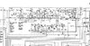
I've been able to rule out the front end by jumpering in the front end from a Pioneer SX-680. Still no Stereo and no change in meter movement. Also, I checked all of the voltages at the transistors on the P200 IF board. They are all slightly low at around 300-400mV less than what the schematic specifies. The only exception was at transistor H205.
Base: 2.177v instead of 3.3v
Emitter: 1.572v instead of 2.7v
Collector: 13.20v instead of 13.6v

However, I did pull and test H205 with a cheap component tester and it seems fine. The hFE and Vf matches the datasheet almost exactly. This is a 2SC1047. I'd really have to search through the scrap pile for a replacement if it came down to replacing it

I also tested all of the diodes on the board in circuit with my multimeter. And, I tested all of the electrolytic capacitors with my ESR meter. They're all within specs.

Beyond that, I'm kinda at a loss as where to go next. I feel like if I knew more about how this all worked, the lack of meter movement would tell me exactly where to look. Can you guys help me out?

One last thought: the regular 2230 tuner section is quite a bit different than the 2230b
 

Attachments

  • Marantz 2230b IF Schematic.jpg
    Marantz 2230b IF Schematic.jpg
    255.4 KB · Views: 16

kellys_eye

Jun 25, 2010
6,514
Joined
Jun 25, 2010
Messages
6,514
Sounds to me more like an alignment issue. The tuned circuits in the IF and detector stages seem 'off'. This isn't an easy fix for the uninitiated and may require test equipment you don't have BUT it's sometimes possible to do a basic realignment by 'ear' and tune each circuit for maximum signal output as you work back from audio to rf stages.

There are Youtube videos on alignment methods you could well to watch.
 

KilgoreCemetery

Apr 12, 2017
258
Joined
Apr 12, 2017
Messages
258
Well, that would explain why I can't find any failed components. I have a signal generator that works, but I've never tested the FM sweep capabilities. I'll have to mark the coils and do some research. Thanks, Kelly!
 

PETERDECO

Dec 19, 2019
239
Joined
Dec 19, 2019
Messages
239
I used to encounter this. It could be a blown RF or IF amplifier stage.
 

bertus

Moderator
Nov 8, 2019
3,330
Joined
Nov 8, 2019
Messages
3,330
Hello,

Sounds to me more like an alignment issue. The tuned circuits in the IF and detector stages seem 'off'.
In the posted schematic I see two ceramic filters and a tuned circuit in the detection section.

Marantz 2230b IF Schematic comment.jpg

Bertus
 

KilgoreCemetery

Apr 12, 2017
258
Joined
Apr 12, 2017
Messages
258
So, I was able to get it figured out to some extent. You were right about it being a calibration issue. I was able to pick up stations close to what the 2230b manual wanted for the calibration steps. So, for 90MHz, I was able to pick up 89.7MHz, 106.1MHz instead of 106MHz, etc.. I was also able to set the 19kHz using the frequency counter on my signal generator. It's definitely better now than it was, but probably still not exactly right. With an antenna, I can get the local station with stereo separation and the signal strength meter has much better movement to it. Without an antenna, it's still pretty limited.

This may be a bit off topic, but I'd like to get a better idea of what I would need to calibrate this correctly. I have a BK Precision 3040 function generator and a Tektronix 335 oscilloscope. After looking over the manual for the BK, I don't think I could set it to 90MHz or anything else in that range. I think the highest it will go is 13MHz. However, it does have AM, FM and Sweep functions, which is confusing. Even after reading the manual, I can't really tell. Will this work for calibrating AM/FM tuners?

Edit: Thanks for the input Bertus and Peter! It took me several hours to type this up between testing and researching and I didn't see the replies until I hit Post
 

Harald Kapp

Moderator
Moderator
Nov 17, 2011
13,738
Joined
Nov 17, 2011
Messages
13,738
it does have AM, FM and Sweep functions, which is confusing.
Why is that confusing?
AM and FM are methods for modulating a carrier signal with a (usually information carrying) signal. That doesn't mean these techniques are limited to radio broadcast in the frequency ranges you can tune to with your receiver.
Using AM and FM as an indicator of the frequency band is one of those quirks in the usage of the English language.
In Germany for example tuners used to be labeled
- UKW for UltraKurzWelle = ultra short wave
- KW for KurzWelle = short wave
- MW for Mittelwelle = medium wave
- LW for LangWelle =long wave
clearly indicating the frequency band.

Note my choice of words: "used to be". Today we find AM and FM, too on our band selector switches ;)
 

kellys_eye

Jun 25, 2010
6,514
Joined
Jun 25, 2010
Messages
6,514
Sweep generators can output a signal that 'sweeps' through the range that your IF (intermediate frequency) works at and thereby allow you to plot the response of the circuit - usually displayed as a 'hump' with appropriately sloped sides and flat top representing the sharpness of the filter (the slope) and the bandwidth (the width of the 'hump') all centred on the IF frequency. In an FM system the IF is usually 10.7MHz so that signal generator would be suitable.

Set the centre frequency to 10.7MHz and the span to (say) 100kHz, feed it into the IF stage and apply the sweep signal. The generator will also have a trigger signal that has to be applied to an oscilloscope that's monitoring the IF output. As the swept frequency moves through the bandwidth of the IF your oscilloscope will display the amplitude of the result and you end up with the 'hump' I mentioned.

You can now tune the system for the correct centre (frequency), width (bandwidth) and response (slope) by adjusting the tuned circuits accordingly.

Yup, not as simple as it sounds! It's often far easier to do this by ear or by using a simple diode probe to monitor the AF level and adjust for the peak accordingly.

That said, most (all?) FM receivers require an antenna - certainly for stereo FM reception - so expecting anything without one is pretty ambitious........ Equally, the location of the antenna makes a difference too. In any modern house there are many sources of interference that can interrupt a decent FM radio signal so try using the set, with an antenna, outdoors and see how it responds.

You might already have tuned the circuitry to its best response already but are lacking the right (correct) operating conditions to prove it.
 

ramussons

Jun 10, 2014
464
Joined
Jun 10, 2014
Messages
464
You have a 19 KHz signal detector after the main demodulation. If that is not properly tuned, it will not detect the 19 KHz pilot and you will not get the "stereo" working, whatever be the local radio receive strength.
Tune to a good stereo station and trim that detector tank till the stereo kicks in.

Your schematic is not complete. In the FM mode, track what turns on the Stereo Lamp. Trace it to the 19 KHz detector and identify the tank LC to be trimmed. It may be in the next board to the right of this.

I don't think it is L202. That may be forming the 10.7 MHz detector for Squelch.
 

bertus

Moderator
Nov 8, 2019
3,330
Joined
Nov 8, 2019
Messages
3,330
Hello,

As @ramussons said, there could be a problem with the stereo decoder.
Here is the decode schematic:
Marantz 2230B stereo decoder.png
Check the parts connected to pin 14 of the HA1156.
See the datasheet for more info.

Bertus
 

Attachments

  • HA1156W_HitachiSemiconductor.pdf
    326.4 KB · Views: 3

KilgoreCemetery

Apr 12, 2017
258
Joined
Apr 12, 2017
Messages
258
Harald Kapp: The confusing part was that it wouldn't tune to frequencies in the FM range, but it sounds like you would just aim for 10.7MHz (for FM) and connect to the IF stage anyways

kellys_eye: That's a lot of good information. I see what you're saying about the 10.7MHz. I tried that, but I didn't know about the trigger signal being sent to the scope and wasn't getting any results that made sense. I'll have to go back and re-test. I think it came out pretty well considering I calibrated it all by ear, but I'd really like to be able to check my work when possible

ramussons: Luckily, I was able to calibrate the 19KHz using the frequency counter in my signal generator. It wasn't off by a whole lot, but adjusting it did make a difference. Thankfully, the service manual comes right out and says where to probe and what to adjust (R304)

bertus: The 19KHz was off by a little bit, but I was able to get it pretty much dead-on. I now get stereo separation if I use an antenna, but not without one. Could the stereo decoder be functional, but weak? Or is it more of a pass/fail situation?
 

73's de Edd

Aug 21, 2015
3,628
Joined
Aug 21, 2015
Messages
3,628
Thir Kilgore Cemetery . . . . . . . . . .(shudder-shudder)

The Signal Strength meter barely moves. We're talking 1-2mm from total static to the strongest station.


Wouldst thou taketh out a roll of pwemium bwewed hooketh up wire and bare it of about 5mm of wire insulation at its end and then string out about 1/2 of a FM wave length of additional wire on out across the bench workspace . Then fire up the unit on FM and tune to the strongest received FM station, and then touch wire end to the marked up RED arrow point and evaluate the sig strength meter for its reading. ( Hoping . . . . that its not being built in a sealed sardine can shielding . )
Then lift and move the wire to the GREEN arrow point and re evaluate the meter reading again.
Is the meter NOW reading MORE, even without the lack of an RF amp stage ?
Your symptoms point to a wonky RF FET . . . . . . causing the signal threshold to fault the adjunct FM steeeeeee-row deficiencies.

upload_2022-3-29_22-30-8.png


73's de Edd . . . . .

upload_2022-3-29_22-27-36.png

.


Last edited:

ramussons

Jun 10, 2014
464
Joined
Jun 10, 2014
Messages
464
Harald Kapp: The confusing part was that it wouldn't tune to frequencies in the FM range, but it sounds like you would just aim for 10.7MHz (for FM) and connect to the IF stage anyways

kellys_eye: That's a lot of good information. I see what you're saying about the 10.7MHz. I tried that, but I didn't know about the trigger signal being sent to the scope and wasn't getting any results that made sense. I'll have to go back and re-test. I think it came out pretty well considering I calibrated it all by ear, but I'd really like to be able to check my work when possible

ramussons: Luckily, I was able to calibrate the 19KHz using the frequency counter in my signal generator. It wasn't off by a whole lot, but adjusting it did make a difference. Thankfully, the service manual comes right out and says where to probe and what to adjust (R304)

bertus: The 19KHz was off by a little bit, but I was able to get it pretty much dead-on. I now get stereo separation if I use an antenna, but not without one. Could the stereo decoder be functional, but weak? Or is it more of a pass/fail situation?
Stereo will not work below a threshold signal strength. So weak signal, no stereo.
 

KilgoreCemetery

Apr 12, 2017
258
Joined
Apr 12, 2017
Messages
258
Thir Kilgore Cemetery . . . . . . . . . .(shudder-shudder)

The Signal Strength meter barely moves. We're talking 1-2mm from total static to the strongest station.


Wouldst thou taketh out a roll of pwemium bwewed hooketh up wire and bare it of about 5mm of wire insulation at its end and then string out about 1/2 of a FM wave length of additional wire on out across the bench workspace . Then fire up the unit on FM and tune to the strongest received FM station, and then touch wire end to the marked up RED arrow point and evaluate the sig strength meter for its reading. ( Hoping . . . . that its not being built in a sealed sardine can shielding . )
Then lift and move the wire to the GREEN arrow point and re evaluate the meter reading again.
Is the meter NOW reading MORE, even without the lack of an RF amp stage ?
Your symptoms point to a wonky RF FET . . . . . . causing the signal threshold to fault the adjunct FM steeeeeee-row deficiencies.

View attachment 54719


73's de Edd . . . . .

View attachment 54718

.


It's about the same on the signal strength meter. I'd say less than 1mm of difference. Also, I don't remember if I mentioned it in the original post, but I did swap out that FET, thinking that it may be a bit dodgy. Next time, I think I'll try testing it your way rather than spending a couple of hours scouring parts units.

Honestly, this is working so much better than it was that I'm happy with the results!
 
Top