Maker Pro
Maker Pro

Make:Electronics Page 85

Mario

Mar 11, 2014
3
Joined
Mar 11, 2014
Messages
3
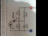
I am new at this so bear with me please. On page 85 of the book, " Make: Electronics ", which I bought to start me off in this new hobby, there is a diagram of a circuit showing a PNP transistor used to light up a LED. There is also a capacitor that is used to make the LED flash. What I do not understand is why is the base of the PNP in the circuit connected between both the 15K and the 27K resistor. Why do we need two resistors and not one to control the base current ?https://www.electronicspoint.com/images/icons/icon5.gif
 

kpatz

Feb 24, 2014
334
Joined
Feb 24, 2014
Messages
334
That's a PUT (programmable unijunction transistor), not a PNP. The two resistors form a voltage divider that sets the gate voltage to about 2.1V, which "programs" the transistor to fire (turn on) at a determined threshold voltage as the capacitor charges through the 470K resistor. Changing those resistors will change the rate that the LED flashes.

It looks like the text below the schematic describes how the circuit works.

I have to say, I've never heard of a PUT before. I had to look it up online. :) I found a similar circuit and its description here: http://www.electroschematics.com/6904/programmable-unijunction-transistor-put-flasher-circuit/
 
Last edited:
Top