Maker Pro
Maker Pro

Magnet Alarm Circuit Board, Battery Power

Status
Not open for further replies.

p1ne

Jun 3, 2015
27
Joined
Jun 3, 2015
Messages
27
This 4.5 V (3 x 1.5 V in series) magnet window/door alarm has 1 internal and 1 external magnet, a Reed switch, and piezo speaker. I've swapped out speaker with blue LED and that works. But when I change battery power to 3 V button cell (which powers LED independently) or 9 V (or even two 9 V in series) with 12 V fan (which also work independently), alarm is not powered. Why aren't these powering the device?
 

Attachments

  • alarm.jpg
    alarm.jpg
    250 KB · Views: 1,525
Last edited:

davenn

Moderator
Sep 5, 2009
14,264
Joined
Sep 5, 2009
Messages
14,264
depends on if you are wiring it all up correctly ??

show us a photo of how you wired it up
 

p1ne

Jun 3, 2015
27
Joined
Jun 3, 2015
Messages
27
I wired it up correctly, even changing pos/neg to make sure. Of course I'm wiring direct to 3 V or 9 Volts, whereas original has battery holder for 1.5 V buttons.
 

hevans1944

Hop - AC8NS
Jun 21, 2012
4,886
Joined
Jun 21, 2012
Messages
4,886
So, if you wire it back the way it was, including the piezo sound transducer, without the blue LED or the other batteries... just the three button cells,,, does it still work? Or have your managed to brick it with your battery adventures?
 

p1ne

Jun 3, 2015
27
Joined
Jun 3, 2015
Messages
27
Yes sir it still works wired back the way it was, with piezo and 3 button cells. Thanks for advice.
 

hevans1944

Hop - AC8NS
Jun 21, 2012
4,886
Joined
Jun 21, 2012
Messages
4,886
Okay, so you didn't brick it yet. And now you want to replace the three button cells with a 3 V battery and use the 9 V battery
(or perhaps two in series) to energize something else, like your 12 V computer fan, perhaps using the reed switch in this device? Is the reed switch the little blue thingy at the top of your photo? Is the only purpose of the circuit board to sound the piezo transducer when the reed switch opens (or closes)? If so, why do you even need to power this puppy up? Just wire your 9V (or 18 V) battery in series with the reed switch and whatever external load you want to drive. How are you going to power the 12 V fan? I don't think it will run very long on two "transistor radio" batteries.

Someone here a few months ago had a similar problem with an RF remote door-bell. He wanted it to operate a small relay that would then ignite the motor in a small model-rocket. No schematics, but he too noted that he could light a blue LED with the door bell speaker output... which may also have been a piezo transducer like yours. After farkling around with it he got an external relay to operate, pretty much by trial and error. End of story. Neither one of us ever found out why it worked, it just did, which was "gud enuf" for him.

Is your window sensor part of a wireless alarm system, or is the piezo sounder the only alarm indication?
 

hevans1944

Hop - AC8NS
Jun 21, 2012
4,886
Joined
Jun 21, 2012
Messages
4,886
I am interested in this because a few years ago I purchased some wireless sensors at Lowe's after a burglary at my home. Some were stand-alone sensors with piezo alarms, others broadcast alarms to a G.E. receiving station which also had a piezo alarm. I never did figure out how to get a contact closure or a signal to drive an external relay from any of the sensors or the G.E. receiving station, so I put the pieces aside until I had more time to work on it. Maybe now is the time to open those puppies up like @p1ne did with his and find out what makes 'em tick... or screech. I don't have any blue LEDs.
 

p1ne

Jun 3, 2015
27
Joined
Jun 3, 2015
Messages
27
hevens, taking apart your GE receiving station sounds like a good idea.

I'm just doing this for fun, to learn. The blue thingy is LED. Reed switch is in back of CB, not pictured, but that doesn't have anything to do with battery connections. I just mentioned it in explaining device: magnets in proximity close Reed switch and complete circuit; when magnets are apart, Reed switch is open and piezo alarms.

In circuit board picture, red wires go to device, blue to power. Pretty simple. As mentioned though, neither the 3 V button/LED, nor two 9 V in series/12 V fan are working when connected to CB wiring, and I've tried all combinations of pos/neg. Also as mentioned, in testing, the latter all work connected directly to battery (no cb). And yes the original still works, so device is not bricked, nor do I care if I brick it (cost $1).

Ideas appreciated to get this working.
 

hevans1944

Hop - AC8NS
Jun 21, 2012
4,886
Joined
Jun 21, 2012
Messages
4,886
It sounds to me like the two red wires have some sort of alternating current signal, perhaps superimposed on a direct current "bias" that may be deliberate or inadvertent, when the alarm is sounding. The piezo transducer will not operate on direct current (but a small DC bias won't hurt it either), so the CB must also contain some sort of oscillator to make the piezo produce sound during an alarm condition. If the reed switch is normally open, and is held closed by the external magnet (the long white plastic thingy), the switch is NOT in series with this oscillator and the piezo disk.

I would have designed it so the reed switch, when it opens, turns on the oscillator and that directly excites the piezo disk. This is a little more difficult to design because you need to sense when a normally closed switch opens. That requires a small current pass through the closed switch at all times, which will limit the battery life unless the current is very, very, small. So, the absence of that small current "triggers" the oscillator to turn on and sound the alarm when the reed switch opens. You are able to "light" an LED with this signal because (1) the current source is small and (2) the LED acting as a diode rectifies the AC signal that was applied to the piezo disk.

So, if you don't need the audible alarm function (or if you can provide it in some other remote location), hack the CB to find the reed switch and cut the traces to the rest of the circuit to isolate the reed switch terminals. Solder two insulated wires to the reed switch terminals and thread them outside the case to your external batteries, fan, etc. No need to use the button cells or the CB inside the case for anything.

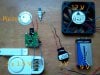
You said there was also a magnet inside the case. That is unusual for a consumer product. Usually there is only a single external magnet (the long plastic object you secure to the window sash) that holds the reed switch closed until it is physically separated from the switch by raising the window. Commercial alarms often have a "bias" magnet inside the case that works in conjunction with the external magnet as an anti-tamper device to prevent someone from defeating the sensor by simply bringing a strong magnet nearby. Can you provide a picture of where the internal magnet on your sensor is located with respect to the reed switch? If this has an anti-tamper feature for one dollar, I would like to know where to get one!
 

hevans1944

Hop - AC8NS
Jun 21, 2012
4,886
Joined
Jun 21, 2012
Messages
4,886
Yeah, Colin, I was suggesting he cut the traces to the reed switch, solder a pair of wires onto it, and use that circuit to control his fan. Don't even use the circuit board for anything except to hold the reed switch. No batteries needed in the original alarm. He may need an external relay and battery though, since the reed switch is normally closed by the sash magnet in the "non alarm" window closed condition. Depends on what he wants to do under "alarm" conditions when the reed switch is open.

Don't you just love hacking this junk? Three button cells, a piezo-electric transducer, a reed switch, and an oscillator that turns on when the switch opens... all that for one U.S. dollar! I can't even buy a reed switch in the U.S. for a dollar! Or three button cells for that matter. How do the Asians do it?
"
 

p1ne

Jun 3, 2015
27
Joined
Jun 3, 2015
Messages
27
Thanks guys, I'm attaching close-ups of reed switch (back), front of CB, and string of LED lights attached to device that works great. What I thought was internal battery (black cylinder) is not; it's what the external magnet is attracted to though. Does this cylinder have oscillator crystal?

Because circuit is oscillator, is that why piezo sound "pulses"? Also, how can 4.5 V produce 80 V circuit? What values would resistors and capacitor be on CB? What does the big square chip do? And is J6 a transistor? Thanks.
 

Attachments

  • reed-switch.jpg
    reed-switch.jpg
    232.3 KB · Views: 1,034
  • alarm-cb.jpg
    alarm-cb.jpg
    268.3 KB · Views: 1,312
  • lights.jpg
    lights.jpg
    104.7 KB · Views: 683
Last edited:

p1ne

Jun 3, 2015
27
Joined
Jun 3, 2015
Messages
27
Someone please respond about how is this an oscillator, and RC or crystal type? The piezo alarm "pulses." Is this PWM?
 

davenn

Moderator
Sep 5, 2009
14,264
Joined
Sep 5, 2009
Messages
14,264
Someone please respond about how is this an oscillator, and RC or crystal type? The piezo alarm "pulses." Is this PWM?

who knows ??
I don't see any PWM circuitry or a crystal
most of the work is probably done inside that black IC cant quite make out the type number on it YL3 xxx doesn't appear to be anything I'm familiar with
 

p1ne

Jun 3, 2015
27
Joined
Jun 3, 2015
Messages
27
thanks for responding. YL3710 I couldn't find anything on that either. Does the piezo make pulsing sound because circuit is RC oscillator? Is J6 transistor?
 

davenn

Moderator
Sep 5, 2009
14,264
Joined
Sep 5, 2009
Messages
14,264
Is J6 transistor?

possibly, but what type Im not sure ... there's around 10 devices that I found that use the J6 SMD code

too much info lacking to give good advice, unfortunately


D
 

p1ne

Jun 3, 2015
27
Joined
Jun 3, 2015
Messages
27
Does the piezo make pulsing sound because circuit is RC oscillator?

Oscillators have to do with tuning to a specific or range of frequencies, so why is a magnet motion detector an oscillator circuit?
 
Status
Not open for further replies.
Top