Maker Pro
Maker Pro

Logitech T-RB22 trackball button repair

jazzo

Jan 17, 2014
7
Joined
Jan 17, 2014
Messages
7
Hello guys, this is my first post on this forum. First of all let me say that I know very little about electronics, so apologies if the terminology I use is not accurate.
OK, so this is what I am after. I have an old trackball (Logitech T-RB22 and here is a link http://www.logitech.com/en-gb/support/4751?crid=399) and it has developed a problem:
basically the main left clik button - although it still physically "clicks" - it doesn't register it, meaning that if I click sometimes nothing happens. Now, I have opened that up
and I think the problem was mechanical so have added a piece of folded aluminium foil between the button and the pin that button is supposed to push for the click to happen. It actually worked, it got better but it wasn't perfect, so I have glued another small piece of aluminium foil to is, but unfortunately the glue got inside the connector and the pin got stuck, so now I have to replace it So, here are a few pictures of the connector (I call it connector but who knows what it is) that I need to replace. It is soldered to the circuit so I will have to cut the metal connectors and solder a new one.
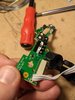
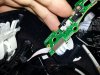
The first picture button.jpg is the button that will push the pin of the connector is to generate a click.
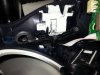
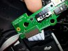
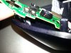
Connector.jpg is what I need to replace. The other connector pictures are different sides and in connector2.jpg you can see the infamous pin that is pushed all the way in.
As you can see it has a 456C printed on it, whatever that means, and also there is a white cover on it - it's visible on the right side of the button.jpg - with a code on it that says 002069-0000 cav4
I googled all this but I couldn't find anything. DO you guys know:
-where and if I can buy this component
-once bought if it can be replaced
-if there is anything I have to be careful to when I replace it.
No point contacting Logitech because they don't produce this trackball anymore.
Any idea?
thanks
 

Attachments

  • button.jpg
    button.jpg
    48.5 KB · Views: 993
  • connector1.jpg
    connector1.jpg
    51.6 KB · Views: 1,166
  • connector2.jpg
    connector2.jpg
    42.6 KB · Views: 1,019
  • connector3.jpg
    connector3.jpg
    55.7 KB · Views: 998
Last edited:

(*steve*)

¡sǝpodᴉʇuɐ ǝɥʇ ɹɐǝɥd
Moderator
Jan 21, 2010
25,510
Joined
Jan 21, 2010
Messages
25,510
These trackballs are very popular with people that have certain issues (I have a work colleague who has several to last him as long as he can...)

I've tried looking for a replacement, but I can't find anything that looks the same.

What you need to do first is to establish what the leads to the switch do. Measure the resistance between them when the switch is not pressed, and again when it is pressed.

You may have to use a different switch positioned "just right" to intercept the button press and with wires leading to the appropriate points.

On the other hand, someone may be able to point to possible replacement parts :)
 

jazzo

Jan 17, 2014
7
Joined
Jan 17, 2014
Messages
7
Thanks for getting back to me. Maybe naively I thought that I could get exactly the same switch from somewhere :)! So you saying to measure the distance between the two components, but the problem is that they are at about 1-2 mm distance when the trackball is reassembled and that's just a guess though because I couldn't think of a way to accurately measure the distance, in fact I can't even see the components (button and switch). The only way to see them is to disassemble it as you can see from the picture.
So from what you are saying I don't need to get an exact replacement, but even a similar one ?
When I googled it, I used these search terms (because I don't know any better really :)) "456C switch" but I didn't really get anywhere.
So I wonder:
1)what's the correct name for that component?
2)is there a specialized shop (online retailer or even a normal high street shop) where it is likely that I could get either this or a similar component?
3)if I get a similar one, how do I know that it will be the right one?
 

(*steve*)

¡sǝpodᴉʇuɐ ǝɥʇ ɹɐǝɥd
Moderator
Jan 21, 2010
25,510
Joined
Jan 21, 2010
Messages
25,510
No, you need to get a multimeter and measure the resistance so we know which contacts are switched when you press the switch.

I looked through quite a number of tactile switches here, but I didn't find anything that looked right.

You know it's right because it looks the same, has the same connections, and the datasheet tells you it actually is both of these things :)
 

jazzo

Jan 17, 2014
7
Joined
Jan 17, 2014
Messages
7
ahhh, I see! Can't imagine your face when you read my post :)! OK I see what you mean now. I don't have a multimeter, but I had a look on ebay and found a cheap one. Is this what you were thinking about yeah? http://www.ebay.co.uk/itm/Digital-L..._Measurement_Equipment_ET&hash=item53f1c8bba5
One thing though, I don't know if I will be able to measure anything with the multimeter because the little pin is stuck in, so it's like the button is permanently clicked.
If so I will buy it, although I have no idea how to use it. Would I be able to use it for other things as well?
Finally, would it be better to wait till we find a switch that looks like that before I buy the multimeter?
thanks for you help, and sorry for the dumb questions...
 

(*steve*)

¡sǝpodᴉʇuɐ ǝɥʇ ɹɐǝɥd
Moderator
Jan 21, 2010
25,510
Joined
Jan 21, 2010
Messages
25,510
ahhh, I see! Can't imagine your face when you read my post :)!

Nah, it's just a case of me thinking "how can I explain myself more clearly?"

That looks fine. If you know where to look you can find meters that are slightly cheaper, but that looks like excellent value for the money.

One thing though, I don't know if I will be able to measure anything with the multimeter because the little pin is stuck in, so it's like the button is permanently clicked.
That is a problem, but even measurements with the button pressed, and images of both sides of the board, we should be able to come to some sort of understanding of what's going on before we try to fix it.

It's also worth knowing that you'll need access to a small soldering iron, solder, and miscellanea like hookup wire, side-cutters, etc. These all add to the cost of repair, and although you might use them again (do you expect to) at some point you might have to consider buying another trackball (assuming a suitable one is available).

Another option is to find someone (ebay?) with a broken one, but where this button still works. Swapping parts from one to the other will ensure you have the right part, so you won't have to do any measurements -- but you still need the soldering iron and solder -- unless this whole board can be replaced.

I do remember googling for this problem and finding a few hits. I must have failed to post a link because several people were saying they had fixed mouse button problems, but you would have to check it's the correct button as you appear to have three different types of switches on this board!

OK, here are some of the links I found: here, and here. (I googled for "logitech trackball button repair"). The first one which I saw, but was obviously too busy to read yesterday, actually has the part number for the tactile switch you need! It's an Omron D2FC-F-7N.

OK, so can we find one of those for you. (The article says his local electronics store had one, but I think he was either lucky or has a *very* good local store.)

So eBay is actually an option (poor, as it turns out) http://www.ebay.com/bhp/omron-d2fc-f-7n The issue is that the switch looks different (it has leads coming out the bottom rather than the side). Hey there's lots, so they must be used for *something*.

But knowing it's a microswitch rather than a tactile switch, that may help... And damn, I just realised that the actuator is not what I thought it was. I'd seen this thing several times and dismissed it as the wrong thing!!!

Does this look like it? You'll need to look at the datasheet here. It has all the specs on the device. You'll probably want a D2F-F because that has the 75g actuating force rather than 150g. The next thing is whether it is jeft facing or right facing. See page 4. This will essentially determine which end the actuator is positioned near when the switch is correctly placed on the board. My guess is that you want the left handed version. If this is correct, the part number you need is D2F-F-A1

Once we have the part number, we can find suppliers as if by magic! It appears this part is out of stock for most suppliers listed here. Element14 has it. Note that eBay doesn't!

But PLEASE check the physical dimensions before you get too excited.

If so I will buy it, although I have no idea how to use it. Would I be able to use it for other things as well?
Yes, you could use it for *many* other things. The question is, are you likely going to want to do any of those things...

(the multimeeter question may be moot now since we've found the original part, or at least one that's *very* similar.)

Finally, would it be better to wait till we find a switch that looks like that before I buy the multimeter?
Possibly, unless speed rather than cost-efficiency is your number 1 priority.

thanks for you help, and sorry for the dumb questions...
It's fine. As I said, I have a colleague with several of these and he has worn a few out. Maybe this thread can help him and others in the same basket.
 
Last edited:

(*steve*)

¡sǝpodᴉʇuɐ ǝɥʇ ɹɐǝɥd
Moderator
Jan 21, 2010
25,510
Joined
Jan 21, 2010
Messages
25,510
Oh, and I've renamed your thread to make it describe what you're trying to do.
 

jazzo

Jan 17, 2014
7
Joined
Jan 17, 2014
Messages
7
Hi there,
Thanks ever so much for your help, that’s a lot of good info there!
Good, so if I don’t need to buy a multimeter then it will save me a fiver : - )
By reading the datasheet – and obviously skipping over all the technical details that mean absolutely nothing to me – I can confirm you are right and the one I need is the left handed version, so that the pin (which I think is what you more appropriately call the actuator) is on the left because the button is positioned on the left of the trackball.
I knew about the soldering equipment, thanks, I will have to buy one because I don’t have any. That I will definitely reuse in the future.
So the only thing is now to look for a UK based supplier (I noticed there is one in one of the links you posted, http://uk.farnell.com/jsp/displayProduct.jsp?sku=1961092&CMP=GRHB-FINDCHIPS-1006741&CIC=gb so I might check the size – now, that will be an interesting exercise: how would I physically measure the switch without breaking it -and then buy it)
Now, I have 2 more questions that haven’t occurred to me before:
1)how do I proceed for the removal of the old switch? The three metal connectors are inserted (probably soldered) in the circuit board (can’t remember off the top of my head whether there is any trace of lead or whether they are wave-soldered), so how would I safely remove them leaving the right space to insert the new one? I suppose I can’t just cut the connectors and leave the end bits inside the circuit. You have mentioned a side-cutter (which needless to say I don’t have so I might need to look for one), would that do the job?
2)There is one more thing (I think I vaguely mentioned this in one of the previous posts). Before I stupidly managed to get the actuator stuck in because of the superglue, I have noticed that even if the button was pressing the actuator the device didn’t register the click, but after having added some aluminium foil between the actuator and the button – to essentially reduce the physical distance between the button and the actuator – the button worked better although it wasn’t perfect. So, my question is, do you think it is better to get a switch whose actuator protrudes a bit more, or is that standard?
And thanks again for your help!
 

(*steve*)

¡sǝpodᴉʇuɐ ǝɥʇ ɹɐǝɥd
Moderator
Jan 21, 2010
25,510
Joined
Jan 21, 2010
Messages
25,510
I might check the size – now, that will be an interesting exercise: how would I physically measure the switch without breaking it -and then buy it)

Estimation is going to be reasonable. What is it's height, width and depth, how far apart are the pins, etc. Does that match with the datasheet?

how do I proceed for the removal of the old switch?

Use some side-cutters to cut the wires, remove the switch , then remove the pins one by one. Use some desoldering braid to clean up the holes so you can get the new pins back in. Don't overheat the board or you might damage the copper teacks (so no "digging" with the tip of the soldering iron.

You probably want to get some practice on something else beforehand.

or is that standard

Yep. At worst, perhaps the plastic that presses against it has been damaged. Maybe you can fix it if it has. But don't try to modify the switch. As you've discovered, that's bad juju
 

jazzo

Jan 17, 2014
7
Joined
Jan 17, 2014
Messages
7
fab thanks, I will start by buying what I need. A soldering iron of 40W should do I think, then the side cutters and the braid and obviously the switch. I will get in touch when I have everything, and post again on this thread if that's ok
thanks a lot for your help
 

(*steve*)

¡sǝpodᴉʇuɐ ǝɥʇ ɹɐǝɥd
Moderator
Jan 21, 2010
25,510
Joined
Jan 21, 2010
Messages
25,510
Yep, posting here would be most appropriate.

See if you can get some old discarded electronic device that you can use as a practice for removing parts. A board from a discarded TV or VCR would be best because these may be old enough to still have a sufficient number of through-hole parts.

What you need to do is to be able to remove components, then clean up the pads so you can see through the holes, all without destroying the pads.

Oh, you'll need some solder too. Get some 60/40 solder (with lead if you can -- lead free is a pain). 0.7mm is great. But up to 1mm is also fine (2mm at a push). Anything smaller than 0.5mm is probably too fine.

The desoldering braid should be at least 2mm wide, and up to about 4mm. Watch out when you're using this stuff. A beginner mistake is to either burn your fingers (it conducts heat really well) or to melt the edges of the plastic spool (same reason).
 

jazzo

Jan 17, 2014
7
Joined
Jan 17, 2014
Messages
7
thank you very much for all the info, very very useful. Oh, I thought of something and maybe you could tell me what you think about it, it's something that occurred to me this morning. You how we said that I will have to cut the metal connector with the side-cutters to remove the switch, but what about removing instead the whole switch without cutting the pins, would it be easier? What I mean is to use the same technique you described, so use a soldering iron to melt the solder that holds the switch in place, then remove the switch and clean the holes with the braid. So essentially I remove the soldering when the switch is still attached, but I do it from the other side of the circuit board where the solder is visible. How about that?
thanks
 

(*steve*)

¡sǝpodᴉʇuɐ ǝɥʇ ɹɐǝɥd
Moderator
Jan 21, 2010
25,510
Joined
Jan 21, 2010
Messages
25,510
The problem with removing the switch intact is that you need to free up each of the three pins. Whilst this can be done, it's a lot easier to cut the pins, and pull them out with a pair of needle nose pliers after melting the solder. This also poses less risk to the board.

It is typically best to pull the pin through from the opposite side to the one with solder. If you've failed to heat the solder enough there is less risk of lifting pads. However in this instance I thought the board was double sided (I may be wrong)
 

jazzo

Jan 17, 2014
7
Joined
Jan 17, 2014
Messages
7
Brilliant, thanks again for all your advices, I will do what you said and post back :)
thanks
 

Saarkin_Cho

Aug 16, 2016
1
Joined
Aug 16, 2016
Messages
1
Apologies for the 2 year necro on the thread, but is seems to be one of the few left discussing repairs of the T-RB22 that came up on google, and re-posting it here so the information is still available to others.

I posted this information in the logitec forums a while ago in a long running thread that was still active, but I assume they deleted it after people started discussing viable replacements that were not from Logitec.
(https://forums.logitech.com/t5/Mice...ll-T-RB22/td-p/987005/highlight/false/page/13)
It was stated in the thread that other threads discussing repairs, and people offering to help others, were confirmed deleted in the past as "offering a service".


Here is some repair information compiled over the last few repairs of my Cordless Optical Trackman/T-RB22 trackball mice.

I use these switches in both my older T-RB22 with the black base/silver top, and the newer revision with the red base/black top.

For anyone having issues with the switch contact resistance, or de-bouncing issues (ie. having to press hard after the button clicks to get the switch close to register, multiple rapid clicks when you press or hold the button, ect.)here are some switch PN's you can use to replace the failed ones.


Left Mouse Button- Can Use E-Switch (SS075Q103F020V1A) and delete the lever.

It use to be in stock at Digikey, but when I last checked, they were out, and they have an 11 week lead time.
I ordered a small quantity in the past, when they had them in stock, unsure if you still can with them coming from the factory.
I Could not find any small quantities for an exact OEM switch, but this is almost the same thing, with a easily removable lever.
Not 100 percent sure, but I think the 20 gram actuation force is taking into account the lever, which when I removed it, felt around the same as the original switch.


MMB, Forward,Back Buttons- Uses Zippy (DS-P1L-00D-Z)

Normaly can't find small quantities, but Derf Electronics has them for a minimum order at the time of this posting. I had to get about 30 of them to meet it, but it is still cheaper than a whole new mouse, or buying 10000 of them.
http://www.zippy.com.tw/sw/show_detail.aspx?ps_rfnbr=288#Specifications
http://derf.com/search/?part=DS-P1L-00D-Z&Submit1=


There are other manufactures, of that style of switch, but the case height is only 3mm vs the 4.5mm of the OEM switch, and would require an extension of the plastic on the external buttons to make up the 1.5mm difference.
3mm alternative example- E-Switch (TS20100F070S) http://spec_sheets.e-switch.com/specs/Q930000.pdf


I Have not replaced the RMB, PGup, PGdn, Lock, so I have no sourced replacement part numbers for them.


There was one instance where the switch was not clicking (audibly or electrically) when pressing the LMB, and replacing the switch solved it, even with the worn grove in the plastic external button. This may just be a stop-gap, and material will need to be added later to flatten out the grove.

The trackball itself is 44mm in diameter in case anyone comes across another mouse we can salvage them off of.

If your having a hard time moving the trackball freely, even after cleaning, one or more of the 3 interference fit jewels that the ball glides on may be pressed too far into their sockets over time.
This can be fixed by drilling or poking a tiny hole on the opposite side of the socket, inside the shell, and using a sewing needle to carefully push the spherical jewel back out of the socket.
Do this in a bowl, As the jewel is tiny, and rolls very easily, and most likely will pop out all the way. It does not need to protrude much, maybe about .5mm or so.


Saarkin
 

Wuu

Feb 28, 2018
1
Joined
Feb 28, 2018
Messages
1
For all of you who love this amazing device and need to repair it and for myself when I will have to repair it in the future, I write down the parts needed to repair the Logitech Trackman T-RB22 (old series black/silver).

I have used the Trackman it for about 18 years! Till the micro switch broke. Has anyone heard about a mouse working half so long?

I can’t use a common mouse anymore. Logitech stopped to produce them. Last pieces in the world cost from 250 Euros up to 1000 US dollars. The last price included the freight. Fair! :D


The micro switch for the mostly used left button: OMRON D2F-FL-A1.
You will have to remove the lever (takes 10 seconds). Cost of the part is about 1 Euro or 1 US dollar.

If you have luck you’ll find OMRON D2F-F-A1 or OMRON D2F-01F-A1 both without the lever.
The ‘F’ in the 2nd part of the number means force 0,74 N. It seems to give the same resistance the original one used to have. If there is no ‘F’ the force is 1,47 N, which probably could be acceptable too.
‘L’ or’ L2’ or ‘L3’ or ‘L30’ are deferent kinds of levers. All can be accepted as you will remove them.
‘A1’ in the last part of the number is important and means ‘left-angled’.
There are also D2FS switches but their declared durability is 100 000 clicks (vs. 1 000 000 of the D2F series).


As I often dismounted my device in order to fix the wiped off button that pressed the switch, I finally damaged the ribbon (the cable or tape connecting the upper and the lower parts). I’ve found a similar thing (just a little bit longer): Wurth Elektronik WR-FFC Rm: 1 mm Pin: 14, 1 A, 686614200001. The price at Conrad was about 4 Euros.
 

federicoz45

Sep 23, 2018
1
Joined
Sep 23, 2018
Messages
1
For all of you who love this amazing device and need to repair it and for myself when I will have to repair it in the future, I write down the parts needed to repair the Logitech Trackman T-RB22 (old series black/silver).

I have used the Trackman it for about 18 years! Till the micro switch broke. Has anyone heard about a mouse working half so long?

I can’t use a common mouse anymore. Logitech stopped to produce them. Last pieces in the world cost from 250 Euros up to 1000 US dollars. The last price included the freight. Fair! :D


The micro switch for the mostly used left button: OMRON D2F-FL-A1.
You will have to remove the lever (takes 10 seconds). Cost of the part is about 1 Euro or 1 US dollar.

If you have luck you’ll find OMRON D2F-F-A1 or OMRON D2F-01F-A1 both without the lever.
The ‘F’ in the 2nd part of the number means force 0,74 N. It seems to give the same resistance the original one used to have. If there is no ‘F’ the force is 1,47 N, which probably could be acceptable too.
‘L’ or’ L2’ or ‘L3’ or ‘L30’ are deferent kinds of levers. All can be accepted as you will remove them.
‘A1’ in the last part of the number is important and means ‘left-angled’.
There are also D2FS switches but their declared durability is 100 000 clicks (vs. 1 000 000 of the D2F series).


As I often dismounted my device in order to fix the wiped off button that pressed the switch, I finally damaged the ribbon (the cable or tape connecting the upper and the lower parts). I’ve found a similar thing (just a little bit longer): Wurth Elektronik WR-FFC Rm: 1 mm Pin: 14, 1 A, 686614200001. The price at Conrad was about 4 Euros.

Wuu I would like to thank you for this advice. I own two tr-b22 and both afflicted by the main switch issue.
I bought the Omron D2F-F-A1 on Digikey and they fits perfectly. Unfortunately, the switch cost 2 euros, but the shipment from US to Italy cost 23 euros but it worth the cost. Thanks man great job.
 

willinliv

Dec 9, 2021
1
Joined
Dec 9, 2021
Messages
1
Thanks for raising the thread - I don't know if discussed elsewhere online but this showed up first in Google. I also had this issue with the left click all of a sudden working sporadically - if really pressed it or wiggled finger on button it would register but not reliably. I had a few microswitches lying around from an old project and they looked like the ones recommended above with three pins. They weren't right angle pins but I managed to cut the old switch out in such a way as to solder the legs of the old to the new. Getting into the mouse was easy enough, unscrewing the bottom section, then unscrewing the top button assembly board (2 screws), I then chose to pull out the ribbon cable connecting top to bottom, as easy enough to reinsert carefully. The top button assembly looks complex but is held together reasonably well and just slides out revealing the microswitch that needs replacing, this has a plastic holder over it holding it in place that just pulls up, I then turned this over to the other side of the board to hold the replacement switch in place as I soldered it in. I don't know the details of the switch (I had to use plier to remove it's clip) but it seems to work very well. I noticed that there was a notch forming on the inside of the plastic button over the switch but the new switch seems to be clicking fine now. I didn't notice the bits in the other post about the 'jewel' to help the ball to glide, so that might be a job for microswitch 3 whenever that needs fitting! Incidentally for me probably only the left, and to a lesser degree right buttons get used, all the others are too much of a stretch for my hand even the scroll wheel, don't know if others feel the same?
 

Attachments

  • PXL_20211209_185251021.jpg
    PXL_20211209_185251021.jpg
    198.4 KB · Views: 2
Top