Maker Pro
Maker Pro

Lock in amplifier EG & G 5210

rags

Jul 13, 2018
13
Joined
Jul 13, 2018
Messages
13
I have a lock in amplifier EG & G Princeton applied research 5210.

I directly connected a signal generator ( rms 9V) to the reference input of the lock in amplifier. Later I saw that the maximum voltage of the signal allowed to the reference input is rms 5V.

The lock in amplifier is not working now. Can somebody please help me in finding the source of the damage that could have occured.

thanks
 

(*steve*)

¡sǝpodᴉʇuɐ ǝɥʇ ɹɐǝɥd
Moderator
Jan 21, 2010
25,510
Joined
Jan 21, 2010
Messages
25,510
Was it working before you applied that large input?

If so, you'll probably need to take a close look at the input circuitry.

If it's a 5210, it will have the extra multiplier board held in place by two brackets which run across the case. There's 4 bolts to remove, and you'll have to disconnect some connectors to allow you to move it out of the way. Take some photos so you know exactly where to put them back.

The area you need to investigate is the input stage that is in a metal can running along the left side of the unit. I've not been inside this.

I'm not sure, but it may be easier to get at things if you remove the large shielded section in the middle of the unit. You'll need to straighten out the tabs, remove the lid, then remove the board, and finally the rest of the shield box. Again, you'll have to disconnect connectors.

After you've done this, you might be able to remove the side of the input amplifier, but I think it may be better to remove the whole input stage.

Open it up and take some photos.

If this get really sticky I can take mine apart and have a look at it too.
 

73's de Edd

Aug 21, 2015
3,628
Joined
Aug 21, 2015
Messages
3,628
Sir rags . . . . .

See if the unit will work with using the TTL input beside it, or use a function generator, in square wave output mode, set down to a TTL level of output.
Also see if this parts used layout is akin to your unit, with U8 being an LF311H on your unit..

REFERENCE . . . . BOARD PARTS LAYOUT . . . . .

upload_2018-7-13_7-1-7.png


73's de Edd
.....
 
Last edited:

(*steve*)

¡sǝpodᴉʇuɐ ǝɥʇ ɹɐǝɥd
Moderator
Jan 21, 2010
25,510
Joined
Jan 21, 2010
Messages
25,510
Please don't post in two separate threads.

I'll delete your question and the reply in the other thread.
 

(*steve*)

¡sǝpodᴉʇuɐ ǝɥʇ ɹɐǝɥd
Moderator
Jan 21, 2010
25,510
Joined
Jan 21, 2010
Messages
25,510
Also see if this parts used layout is akin to your unit,

That board looks like the one which receives the input after it has passed through what I think is the preamp.
 

73's de Edd

Aug 21, 2015
3,628
Joined
Aug 21, 2015
Messages
3,628
My YELLOW star components relate to the reference oscillator processing portions within that PCB.
It has the U8 doing the squaring of the SINE oscillator, immediately after its input.
Need his confirmation on those parts presences before posting schematic with its signal flow mark up.
Thus, then permitting scope evaluation down the line. Looking at the hi z buffering of those dual input options, I really wouldn't expect a " damaging " problem with his higher level of input. . . .especially on the other TTL INPUT, as it is being diode clamped.

73's de Ed
.....
 

(*steve*)

¡sǝpodᴉʇuɐ ǝɥʇ ɹɐǝɥd
Moderator
Jan 21, 2010
25,510
Joined
Jan 21, 2010
Messages
25,510
It would be very interesting to hear if there is confirmation that it was working previously.

Even if it was, we couldn't rule out that it was around then that a tantalum capacitor decided to pay a may trick (not that I'm fixated on tantalum capacitors, but I've had to replace 4 faulty ones in the last 3 repairs I've done).

I'm sure it's a coincidence, but I'm starting to develop a strange facial tick that starts whenever anyone mentions tantalum capacitors.

I would certainly be checking for excessive current draw from the power supply.

If @rags has access to a clamp on AC ammeter, that's the easiest way to measure the secondary current on the transformer. I think my thread on the 5210 I repaired will quote The values I saw after the faults were repaired.

In any case, I would be verifying the +/- 18V rails to the OP Amps before I bothered to look at their outputs.
 

rags

Jul 13, 2018
13
Joined
Jul 13, 2018
Messages
13
I got the instrument on 10 th July. It looked like it was working well though I did not do any experiment with it. I could carry out the initial procedure (mentioned in the instruction manual).

I thought because of high reference input voltage the device got spoiled. Or may be there is a different reason.
Please see the attached photo of current status. It powers on but no button responds. I am so thankful to you that you have shown interest in my problem.
 

Attachments

  • IMG_3197.JPG
    IMG_3197.JPG
    223.7 KB · Views: 55
  • IMG_3197.JPG
    IMG_3197.JPG
    223.7 KB · Views: 34

rags

Jul 13, 2018
13
Joined
Jul 13, 2018
Messages
13
I am attaching a few photos of the PCB. I am a physics guy with minimum knowledge of electronics. Please bear with me.
 

Attachments

  • IMG_3201.JPG
    IMG_3201.JPG
    384.1 KB · Views: 39
  • IMG_3202.JPG
    IMG_3202.JPG
    381.8 KB · Views: 42
  • IMG_3203.JPG
    IMG_3203.JPG
    383.4 KB · Views: 36
  • IMG_3204.JPG
    IMG_3204.JPG
    371.5 KB · Views: 35

(*steve*)

¡sǝpodᴉʇuɐ ǝɥʇ ɹɐǝɥd
Moderator
Jan 21, 2010
25,510
Joined
Jan 21, 2010
Messages
25,510
I presume you've removed 2 boards from the unit already?

If not, then I have some very bad news for you.
 

rags

Jul 13, 2018
13
Joined
Jul 13, 2018
Messages
13
I had taken the photo after removing the boards.

I have now attached photos with nothing removed.
 

Attachments

  • IMG_3212.JPG
    IMG_3212.JPG
    373.2 KB · Views: 50
  • IMG_3211.JPG
    IMG_3211.JPG
    353.5 KB · Views: 39

(*steve*)

¡sǝpodᴉʇuɐ ǝɥʇ ɹɐǝɥd
Moderator
Jan 21, 2010
25,510
Joined
Jan 21, 2010
Messages
25,510
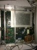
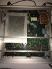
Ok, I'll assume you followed my instructions for removing boards to get at the input amplifier.

If the buttons don't have any effect, then you have broader problems. My first check would be the power supply.

Do you have a multimeter, and how confident are you in its use?

Do you have access to a clamp on AC ammeter?

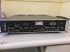
First, check that the voltage has been set correctly. If you remove the power plug and open the sliding plastic cover, you should be able to see the voltage setting on a small board under the fuse. If you need to charge this, pull the board out (it can be very stiff) and rotate/flip it so your mains voltage appears the right way up after you slide it back in.

The next check is a sniff test. When powered on, do you smell any acrid odour coming from the transformer? This is a clear indication of a shorted power supply.

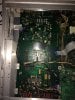
There are several wires leading from the transformer to the main board. After removing any cable tie there is on it, you can use a clamp on AC ammeter to measure the current. From memory you should expect a few hundred mA, perhaps less with the 2 boards removed.

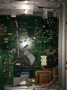
The next step is to measure the voltage on various ICs on the board.

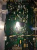
There are a number of 8 pin ICs with part numbers like LM711. If you google the part you can find a datasheet that will show you the +ve and -ve pins. With your meter on a voltage range, and the black lead held against the metal case, the +ve pin should read close to +18V, and the -ve pin should read close to -18V.

There are other ICs with part numbers like 74HCxx or 74Cxx, or maybe 74LSxx. Again, Google these for a datasheet and find the power supply pins the ground (or Vdd) pins will be at 0V compared to the case, and the Vcc, or Vdd pins will probably be close to 5V.
 
Last edited:

(*steve*)

¡sǝpodᴉʇuɐ ǝɥʇ ɹɐǝɥd
Moderator
Jan 21, 2010
25,510
Joined
Jan 21, 2010
Messages
25,510
I had taken the photo after removing the boards.

I am very relieved :)

I have purchased equipment that has been gutted. It doesn't make me happy.
 

rags

Jul 13, 2018
13
Joined
Jul 13, 2018
Messages
13
The main supply line has been set at 220 V and there is no smell from the transformer. I can use a multi meter confidently but I do not have a clamp on ammeter. I am now looking for the IC s you mentioned and should the top board in the aluminium box be removed when I measure the voltages on the ICs?
 

(*steve*)

¡sǝpodᴉʇuɐ ǝɥʇ ɹɐǝɥd
Moderator
Jan 21, 2010
25,510
Joined
Jan 21, 2010
Messages
25,510
There are ways around the lack of a clamp multimeter, and the absence of a smell is good :)

Do all these tests with the boards removed and disconnected.

I've highlighted a few spots on the motherboard for you to check.

IMG_3201b.jpg

Look at the part circled in red. A close-up should look a bit like this:

View attachment 41653

With your multimeter in voltage mode and the black lead on the middle pin (or the tab) of the 7818, you can measure the input voltage on the left pin, and the output voltage on the right pin. The left pin should be at least 22V (it will probably be higher), an the right pin will be close to 18V.

With your black lead on the left pin of the 7918, the input voltage is the middle pin and the output is the right pin. The voltages should be similar to the 7818, but they will be negative.

To check the current, read the voltage across the 27 ohm resistors highlighted by the yellow circle. Th resistors in question have the stripes red, violet, black, gold. I had to replace one of these, but your board will look similar to the image below:

View attachment 41652

With the multimeter in voltage mode, read the voltage across the resistors. They should be similar and maybe around 5V.

The orange rectangle is a place where you'll find quite a few 74 series ICs, The purple circles are probably around LM711's
 

(*steve*)

¡sǝpodᴉʇuɐ ǝɥʇ ɹɐǝɥd
Moderator
Jan 21, 2010
25,510
Joined
Jan 21, 2010
Messages
25,510
And a few questions you can answer for me.
  1. Is there a date of manufacture inside the lid of your unit?
  2. Does your transformer seem to sit nicely at right angles to the side of the unit, or does it sag down a bit?
  3. Did your unit have a piece of paper taped to the top of the large aluminium shield?
 

rags

Jul 13, 2018
13
Joined
Jul 13, 2018
Messages
13
The lid has a number 21593E
The transformer is sitting tightly
There is paper with calibration numbers

I checked the voltages across 7818 and 7918 and they are as you mentioned.
Across the resistors the voltage is around 2.8V
 

(*steve*)

¡sǝpodᴉʇuɐ ǝɥʇ ɹɐǝɥd
Moderator
Jan 21, 2010
25,510
Joined
Jan 21, 2010
Messages
25,510
Across the resistors the voltage is around 2.8V

That indicates a current draw of 100mA on each of the +/-18V rails. That's reasonable.

I'd move on to checking the voltages on the chips in the orange rectangle.
 

rags

Jul 13, 2018
13
Joined
Jul 13, 2018
Messages
13
For Vcc and Metal case the voltages are all about 5V for ICs of the type 74HCxx or 74Cxx, or maybe 74LSxx though I have not checked for all of them yet.

But the voltage across + and metal case and - and metal case for the LM 311N Ic is only about 3.7 V.

thanks
 

(*steve*)

¡sǝpodᴉʇuɐ ǝɥʇ ɹɐǝɥd
Moderator
Jan 21, 2010
25,510
Joined
Jan 21, 2010
Messages
25,510
But the voltage across + and metal case and - and metal case for the LM 311N Ic is only about 3.7 V.

Oooh, that's interesting.

Take a look at more of those ICs. It may be worth putting the large shielded board back in and check some of the op amps on it too.

I might take a closer look at mine to see if there are other regulators.
 
Top