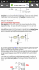
lately I've been thinking of wiring up several regulators so I've been searching for circuits..
using this attached circuit, what keeps 1 regulator from working harder than the other?
is it a result of the 2 diodes and their vf drop? or is it due to the large capacitor(s)?
I'm just not sure how the diode/cap solves the load balancing problem... ?
using this attached circuit, what keeps 1 regulator from working harder than the other?
is it a result of the 2 diodes and their vf drop? or is it due to the large capacitor(s)?
I'm just not sure how the diode/cap solves the load balancing problem... ?

")