.
Sir Mike . . . . .
We confirm the components that you utilized, along with the somewhat uber- healthy selection of the 22K Ufd's of initial raw DC filtering.
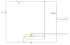
In using our Right Honorable and Esteemed "bigone5500"'s reference schematic, but, with our yet not FULLY knowing YOUR circuitry utilized:
The utilization of secondary C2 and C3 electrolytics are of definite importance.
With manufacturers harping on utilization tantalum types for C3, but I have never found that "cut in stone", with the possiblity of squirrelly operation at some voltage and current nodes.
Also, the selection of the value of R1, as it is directly related to the current limiting and foldback aspect of the 350's internal regulatory circuitry.
Get it too low of a value, and some overiding constant current mode tendencies will start showing up .
Your transformers voltage and current capability spec certainly seems sound, since you are dropping from a hefty raw 12 ++++++ volts all the way down to a 6 VDC level.
But, for further analysis, it would be nice to have feedback of the RAW DC voltage coming into the 350 at sample points of 100 ma-500 ma and your mentioned 800 ma and then at 1 amp . . . and 2 and 3 amps current draw, if the latter 3 levels are now being attainable.
The mention of power dissipation at the full voltage and current condition, and stress on the 350, can be scaled down by the shunting of the input to output terminals of the 350 with a fixed power resistor.
Its ohmmic value is being selected so that half of the power passage current will be will divided beween it and the 350.
With the 350 then saying:
" Wheeeeew . . . .thanks !
The only last thing in mind, might be the quality of the power transformer.
If I had a quality old school Thordarson or Triad power transformer in that circuit . . . . I could expect the FULL rectified raw DC voltage not to drop from that value down to a 12 VDC @ 3A draw. (With it never exceeding a >20 % difference.)
When I evaluate a Radio Shack or other "over the waters" transformers, they come up far short of that spec along with their running hotter.
Standing by for more info from you . . . .
73's de Edd
.


 As "dark side" said, you need the capacitors..