Maker Pro
Maker Pro

Light works with power supply not connected to PCB

muttleytm

Mar 24, 2012
6
Joined
Mar 24, 2012
Messages
6
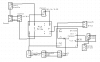
I have a very simple circuit to light up some 12V lights, specifically a dual filament 1157 tail light bulb. One of the filaments connect with the output of a relay for the brake light and the other with another set of connectors for rear tail light and one for headlight.

When switched on both the headlight and the tail light will turn on.

The brake light connected to the output of the relay didn't light when it should so to check this filament and the wiring to it, I plugged the leads for the tail light into the header that I know works for the tail light and headlight. When I do this, the bulb doesn't light.

I figured maybe one of the wires was broken so tested the continuity of the pair of wires for the brake light. For one of the wires I had zero resistance where the base of the bulb contacts the socket and infinite resistance for the two inside contacts. When I tested the other lead for the brake light I got zero resistance for one of the inner terminals and infinite resistance for the other inner contact and where the base contacts The wiring should be good. Thinking that it must be the bulb I tried several others and they didn't light either.

I then took a AC/DC converter rated 12V (I measured about 18V) and hooked its output to the two leads for the brake light and it lights regardless of which bulb I use.

I am baffled.

Does anyone have an idea what may be going on?

Thanks
 

timothy48342

Nov 28, 2011
218
Joined
Nov 28, 2011
Messages
218
You tested your bulbs and at least you know that's not the issue. It was a little hard to tell from your description just what you were testing to get the zero resistance and INF resistance, but the thing is... it has got to be a wiring issue or the contacts in the socket itself.

And you said the tail lights work fine, so the ground has to be good. So it has to be the hot, but where does it come from? Directly from the brake light relay or does it take a detour?

It might be good to look at a schematic in case the electrical pathway is not what is expected. Remember you have a relay for brakes that opperates both lights, but the brake lights are also turn signals and are opperated independently, There has to be seperate controls for that.

Does the brake light work on the other side? Do you turn signals work? Right, left, front back? When the turn signal blinks, does it blink at the same rate as it should and the same rate for both sides?

Just trying to bounce some ideas off the wall. Hope I'm not leading you AWAY from a solution. Car wiring can be a pain, but it's all about isolation.

--tim
 

muttleytm

Mar 24, 2012
6
Joined
Mar 24, 2012
Messages
6
It's for an electric bicycle so there aren't turn signals and only one tail light. The relay is a double pole relay that closes when either the switch on either brake levers is squeezed. One pole is for the brake light and the other triggers an "ignition" cutout.

As for the brake light relay, I have to test the output to the header tomorrow when I will be able to attach some leads to a connector (it's hard to get a voltmeter probe where I need to test it). I think in the case of the relay side of things I have some other issue coming from the motor controller. The relay has a 5 volt coil, and for some reason I'm only getting 3.5V.

But, right now I'm interested in why one of the filaments in the brake light works when it is hooked up the the tailight header on the PCB, but, when I remove this wire and plug in the wire for the tail light side it doesn't light (but does if I apply voltage from my AC/DC adapter to the same wire.

When I do this the wire is in a little different position than when I have it plugged in. I'll try flexing it some when hooked to the adapter to see if maybe I have a break in the wire that is only apparent when in one position.

I
 

timothy48342

Nov 28, 2011
218
Joined
Nov 28, 2011
Messages
218
ok, I was thinking of a car, of course. Heh.

Powering things with the adapter was a good idea. Maybe continue along that strategy, but with a jumper wire from the power source that powers the light. (the battery, I guess that would be? 12? 5v? Whatever would normally go through the relay to the bulb.) Place the jumper wire in different spots along the path bypassing parts of the wiring. Obviously a jumper wire directly to the bulb will light it, but find where it won't.

That relay is suspect since you know it is getting a little less than it should to the coil. So a jumper from the source to just after the relay would tell you if the problem is after the relay or not. A jumper from the source to just before the relay would tell you if the problem is before the relay or not. A jumper from just before the relay to just after (basically bypassing it) would tell you if the relay is the problem.

Am I making sense? Good luck anyway.
--tim
 

davenn

Moderator
Sep 5, 2009
14,260
Joined
Sep 5, 2009
Messages
14,260
It really is time for a circuit from you so we can see what you are trying to achieve. :)


Dave
 

duke37

Jan 9, 2011
5,364
Joined
Jan 9, 2011
Messages
5,364
Strange results can occur with vehicle lights if there is a faulty earth.
If there is no earth to the light cluster, then a low powered light can work by supplying an earth through a more powerful light. In the case of a car, a side light can go out when the brake light comes on. In the case of your bicycle, perhaps you do not have the false earth through another light.

Do you have a circuit diagram?
 

muttleytm

Mar 24, 2012
6
Joined
Mar 24, 2012
Messages
6
On the relay side of things, I think the problem is that the voltage supplied to the coil is too low for the contacts to fully move from the open to the closed position. I measured 3.6V where is is coming from the controller. (it's supposed to be 5) to the coil. When I squeeze the lever and close the switch I don't measure any voltage at the header the brake light connects to. I'm not worried about that for now, though.

I've attached a schematic of the circuit:

Conn 7 is the header that the lights on/off switch is connected to. Positive 12 Volts is supplied to leg #1 from a DC/DC converter. The power travels through the switch and returns to leg 3 of the same header. This leg in turn sends the current to leg #1 of header 10 and 11. Each of these legs leads to either a tail light or a headlight. and the current returns through leg #3 and then back to the negative of the DC/DC converter. They are interchangeable and when the wiring for either the headlight or the tail light or both are connected they light as they should when the switch is closed.

If I disconnect the tail light and headlight and plug the brake light to either header 10 or 11 the light doesn't light. If I disconnected from this header and check the continuity of this wiring I get zero resistance to the ground side of the rear light assembly, infinite resistance to the contact for one of the filaments and zero resistance to the contact for the other filament.

If I hook my AC/DC adapter (rated 12V, measured 18V) to the connectors for the brake light wiring one of the filaments lights up as it should.

I tried flexing the wire while it was connected to the AC/DC adapter to see if maybe there was a break in the wire that only didn't allow current through it when the wire was in a certain position, but, the light didn't blink or change at all.
 

muttleytm

Mar 24, 2012
6
Joined
Mar 24, 2012
Messages
6
This should have the attachment

This should have the attachment
 

Attachments

  • Brake Light and Tail Light Schematic for Normally Open Brake Lever Switches.png
    Brake Light and Tail Light Schematic for Normally Open Brake Lever Switches.png
    9.7 KB · Views: 659

timothy48342

Nov 28, 2011
218
Joined
Nov 28, 2011
Messages
218
So here is what I'm seeing...

Pin 1 on Conn11 is the hot going to your bulb for the tail light. It finds it's way to one of the 2 little brass nubs on the bottom of your bulb.

Pin 3 of Conn5 is the hot going to your bulb for brake light and should reach the other little brass nub on the bulb.

Here is a picture of your bulb if I can manage to link to an image properly:
bulbs2.jpg

That's it right? I want to make sure we are talking about the kind of bulb with 2 little brass nubs on the bottom. It actually has 3 connection, because the outer case is the 3rd connection and should be the ground.

I want to know about the ground connection.

Pin 3 of Conn11 is ground for tail light
and Pin 1 of Conn 5 is ground for brake light
but where do they go? Do they both take seperate paths to reach the outer casing of that bulb?? Is one not used? Are they both in good condition?

The reason I ask is that is 4 connections... (+v tail, +v brake, 0v tail, 0v brake)
... and the bulb only has 3. (+v brake, +v tail, 0v shared ground)

You only need 1 ground, but If you have 2 ground connections and one is broken or not used, then when you disconnect the tail light to test out the brake light you might be disconnecting the one ground that does work. Maybe the brake light is using the tail light's ground. (which is disconnected)

I know it's baffling that you plug in the brake light there and it doesn't work, and you plug it into your ac/dv adapter it does, but... there could be something else happening there. Test the continuity of those 2 grounds if you can, but don't let it distract you too much from the output of the relay.

When you squeeze the brakes, can you hear the click from the relay? Also, I don't see any connection form the controller ground the the relay.

Also, since you tested the output of the controler to be 3.6V, what about the input of the controller? I think it says 20V. Is it getting what it should?

--tim
 

muttleytm

Mar 24, 2012
6
Joined
Mar 24, 2012
Messages
6
I see where my problem is. The brake light wire has pin 1 the negative and pin 3 positive. The tail light wire is just the opposite. So when I plug the brake light in alongside the tail light the positive from the header goes straight to ground. If I unplug the brake light connector and hook it up to my AC/DC adapter it works as I'm not feeding the positive directly to ground on the PCB.

If I run a jumper from one of the positive leads from the tail light/headlight header to the negative post of the brake light header (while the tail light connector is plugged in to complete the ground) I get 12V.

Thanks
 
Top