Lance Mannion
- Jun 9, 2014
- 37
- Joined
- Jun 9, 2014
- Messages
- 37
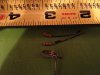
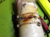
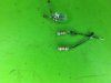
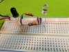
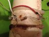
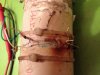
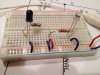
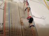
Hi - I'm a newbie here and I'm trying to fix a problem for a friend since I'm a little more mechanically/electronically inclined than he is. Here's the situation...I'm trying to repair an LED optical sensor circuit. The purpose of the sensor was to detect that a golf ball has passed down a return pipe. There were two holes drilled into a PVC pipe and LEDs were pushed through so they were directly across from each other in the pipe. The whole assembly was home built long ago by someone else and when I took it apart, all of the wires to the LEDs and the resistors were corroded so badly I could barely tell how the circuit was set up. Luckily there is an another operational sensor that works at his mini golf course so I could find out the voltage being fed to the LED and the voltage being produced during normal operation (i.e., no ball is passing through the pipe/sensor). The voltage going into the sensor is 5 volts. The voltage being produced is 800mV. Based on this I assume that the one LED is powered with the 5V and the other LED is acting as the sensor and is producing 800mV while the other LED is glowing. When I tested the other working sensor at the course, almost 5 V were produced when I blocked the LED light (i.e., simulated a ball in front of the light LED) I was expecting the voltage to go to 0 but it didn't. I don't dare take the working sensor apart since it's the only one left and it's sealed. I took some pictures of the corroded wires if interested. I included a drawing of what the wire configuration resembled but it can't be right because both LEDs would be lit. I don't know if there was another component inside that disintegrated over the years due to water getting into the components and causing a short. Any help at all on what the circuit could possibly be, would be greatly appreciated. Sorry for the bad drawing ") Thanks!
Thanks!
I put the actual pics of the corroded circuit here : https://www.dropbox.com/sh/pfr0vdwhsbg008r/AACTAc96hfnv_K7mbHfMzHkKa
The yellow wire in my drawing is the white wire in the pics.
Thanks!I put the actual pics of the corroded circuit here : https://www.dropbox.com/sh/pfr0vdwhsbg008r/AACTAc96hfnv_K7mbHfMzHkKa
The yellow wire in my drawing is the white wire in the pics.
Attachments

Last edited: