Maker Pro
Maker Pro

LED driver transistor kind of noisy

osterchrisi

Mar 8, 2011
28
Joined
Mar 8, 2011
Messages
28
Hello!

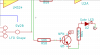
I'm experiencing some trouble with a really simple LED driver with a transistor, I attached a photo of the circuit which sits on the same pcb as an audio circuit.
The problem I have is that the connected LED induces quite an amount of click/pop into my audio signal. I tried different solutions:

- connecting the led to the collector (with resistor of course)
- increasing the led resistor to 1K
- decoupling capacitor from collector to ground

of which only the bigger LED resistor seems to work out. But that of course dims my LED to a certain amount.
Does anyone have any idea on how to approach this noise or at least reduce it to minimum? Or will there always stay a bit of clicking/popping?

Thank you so much for any suggestions!!
 

Attachments

  • led driver.png
    led driver.png
    15 KB · Views: 2,317

duke37

Jan 9, 2011
5,364
Joined
Jan 9, 2011
Messages
5,364
If placing a capacitor across the transistor makes no difference I would suspect that the interference comes from an earlier stage. Try disconncting R58 and see if the problem is still there.
Try better bypassing of the power supply.
Try slowing down the switching device which controls the led.
A possibility is that Q5 is switching a higher voltage than it is capable of doing causing avalanch.
 

osterchrisi

Mar 8, 2011
28
Joined
Mar 8, 2011
Messages
28
The clicking is nearly gone there if I disconnect R58, adding the transistor with LED unconnected makes it quite hearable and then connecting the led makes it worse. The power supply is bypassed pretty well already I have the feeling, at least I wouldn't know what more to do there.

The second suggestion I cannot take because the LED is a simple speed indicator for an LFO, so the speed varies every time the user turns the knob - though we're only talking like (roughly) 0.5Hz to 100Hz here...

And the last one I also don't believe, as I'm only switching 9V here, BC547C should do the trick, right?

Thanks for your answer!
 

duke37

Jan 9, 2011
5,364
Joined
Jan 9, 2011
Messages
5,364
The BC547C can manage 45V so there is plenty of room here.
When I suggested slowing down the switching, it may be that the clicks have a much higher frequency component than the basic circuit is operating at.
A 100nF capacitor from Q5 base to ground would not affect the basic signal (100Hz) a geat deal but will reduce the rapid switching transients. If the led is intended to flash, this is perhaps as slow as you should go. If the led is just intended to show output then a much bigger capacitor could be used.
It would be better to do this earlier in the circuitry where the interference is produced.
 

osterchrisi

Mar 8, 2011
28
Joined
Mar 8, 2011
Messages
28
Mhm, I tried that but the only thing I can really achieve here is slowing down the whole LFO speed by putting a capacitor from either base/gate (Q2/Q5) to ground... Although I start to understand what's happening.

I attached the earlier stage of that circuit where the actual signal is produced and later shaped into sawtooth, pulse or ramp. It's a voltage controlled oscillator, the two resistors in the left (R19/R20) are connected to an opamp summing together different control voltages.

I'll keep searching!
Maybe you can see something else?

//edit:
The ripple induced by the LFO is roughly 10mVpp by the way.
 

Attachments

  • led2.png
    led2.png
    22.4 KB · Views: 655
Last edited:

duke37

Jan 9, 2011
5,364
Joined
Jan 9, 2011
Messages
5,364
The two diagrams you give are not connected so it is difficult to see what is happening.
You say that there is a pulse output, pulses have high frequency components and this could be the source of the noise.
 

osterchrisi

Mar 8, 2011
28
Joined
Mar 8, 2011
Messages
28
Yes sorry... Here's everything that I think is necessary but maybe it's not too easy to understand as there's a DPDT switch involved. Just have a look at it and maybe you have an idea...

Thanks a lot for your help!
 

Attachments

  • led3.png
    led3.png
    15.7 KB · Views: 232
  • led4.png
    led4.png
    6.6 KB · Views: 224

duke37

Jan 9, 2011
5,364
Joined
Jan 9, 2011
Messages
5,364
I don't understand what is going on. In particular,the SQRLFO output comes from a virtual earth so should not have any signal on it. I don't see any pulse output.

You say that there are clicks on the audio signal but the circuit for this is not included. There is some crosstalk between the oscillator and the audio path. When Q2 discharges the capacitor. it will produce a current pulse in the ground track.

I would look at more isolation between the audio circuit and oscillator. It could be coupled via the grounds or the power supply.The two grounds should only be connected at one point. Louder clicks when the led is running is presumably due to larger current pulses.

I doubt if I can help further.
 

osterchrisi

Mar 8, 2011
28
Joined
Mar 8, 2011
Messages
28
Why do you mean that the SQRLFO comes from a virtual earth?

In the end I can simply add a 470uF decoupling cap to get rid of the noise but also I think this is kind of a rough solution for it, no? I always tend to not put too many decoupling caps into the power supply for reasons of not getting too much capacitive resistance for the power supply...
 

duke37

Jan 9, 2011
5,364
Joined
Jan 9, 2011
Messages
5,364
U3B appears to have a 100k resistor from p7 to p4, this, with the 100k input resistor gives an amp with a gain of -1 and a virtual earth (AC) at p4. In fact looking at it again, perhaps U3B is just a comparator with no feedback to give the square wave output. The two output labels seem to come from the same point.

I do not know what capacitive resistance is. If increasing the capacitance reduces the noise, then the capacitance is not sufficient. Any decent power supply should be able to feed into a constant voltage, if it can't, add a bit of resistance before the capacitance. This will obviously adversly affect the regulation.
 
Top