Maker Pro
Maker Pro

LDO heating up

makowka

Jan 17, 2013
4
Joined
Jan 17, 2013
Messages
4
Hi

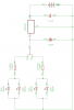
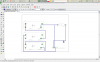
I want to build a circuit like that shown in the picture. I haven't assembled it yet, instead I have made a small test circuit for the LDO to measure its correct operation. I have noticed one thing, if I don't apply the voltmeter terminals to the circuit, the LDO gets very hot with the danger of burning up. As you can see on my circuit, in the neutral switcher state the LDO doesn't have any current consumer to convey its current to. The batteries will be all the time inserted, of course. Do I take a risk of burning the LDO?
 

Attachments

  • circuit1.png
    circuit1.png
    8.1 KB · Views: 132

(*steve*)

¡sǝpodᴉʇuɐ ǝɥʇ ɹɐǝɥd
Moderator
Jan 21, 2010
25,510
Joined
Jan 21, 2010
Messages
25,510
Several problems:

a) you have pairs of LEDs in parallel
b) the resistor in series with the LED drops too little voltage to be effective in limiting the current.

And some questions:

1) does the regulator get hot is the voltmeter probes are not connected?
2) if the answer to (1) is "no", check that you have the meter on a voltage (not current) range, and the probes plugged into the correct positions.
3) if the answer to (1) is "yes", how bright are the LEDs?
4) if the Answer to (3) is *very bright*, then the answer is likely to be (b) above.
5) if the answer to (3) is "off", "disconnected", or "very, very dim", then the problem is likely to be that you have connected the regulator incorrectly.
6) if the answer ti (3) is "normal" then you have most likely got a regulator in a very small package and it is underrated or insufficiently heatsinked, or your battery voltage is too high.
 

makowka

Jan 17, 2013
4
Joined
Jan 17, 2013
Messages
4
Hello Steve

To 1):
I want my device to be portable, so I can't allow to employ an external battery pack. I want to stick to 3xaaa (rechargeable) batteries, which yields 3.6V. In that way I can power two leds at a time with that low voltage.
In my test setup I didn't use capacitors, neither the leds, in the picture you can see my test board. Only power supply, LDO and terminals for the voltage meter. The resistor resembles the voltage meter, since there isn't one in the eagle libraries.
 

Attachments

  • testcircuit.png
    testcircuit.png
    75.5 KB · Views: 147

KrisBlueNZ

Sadly passed away in 2015
Nov 28, 2011
8,393
Joined
Nov 28, 2011
Messages
8,393
Is the battery connected round the right way? Positive to the LDO input? It's drawn backwards on the diagram in your first post.

Also do you have the LDO input and output round the right way? If you connect the battery to the output, you will probably damage it.

The LDO shown in the second diagram, are the connections shown viewed from above or viewed from below?
 
Top