Maker Pro
Maker Pro

Laser Driver Troubleshooting?

Noura

May 13, 2014
19
Joined
May 13, 2014
Messages
19
Hi everyone, I'm new to this forum. I made an account specifically to ask this question (haha.) I'm pretty new to this stuff, as started tinkering in January and fell in love. I'm self-taught so I acknowledge that there are gaps in my knowledge.

I am attempting a laser pointer, and am at the point where I'm breadboarding the driver circuit. Maybe I'm misunderstanding the point of a driver, but shouldn't it be significantly reducing the voltage going to the diode? I put some probes at the end of the circuit and hooked them to my meter, and it's still almost the whole 9V that I powered it with (something like 7.5V way too much for a 3V laser.)

I figure that there must be four possibilities: one, I'm probing the wrong spot; two, I wired something wrong; three, I should power it with less voltage; four, I'm misinterpreting the point of this circuit.

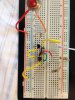
Anyway, I'm going to post the circuit diagram and the breadboard I put together. Let me know if I need another angle of the breadboard; it seems clear to me but then again I put it together hahaha. Ignore that part with the toggles and LEDs, that's another thing.Screen Shot 2014-05-12 at 8.33.27 AM.png IMG_5839.JPG
And if you don't feel like looking at my messy circuit and just know some common mistakes/can figure it out from the description, I will appreciate any and all help so comment away.

Thanks!
Noura :)
 

kpatz

Feb 24, 2014
334
Joined
Feb 24, 2014
Messages
334
The circuit you posted regulates current, not voltage. This is what you need for a laser diode, but measuring the voltage across it while open-circuit won't give you the expected results. Connect a load across the output (such as a 10 ohm resistor) and measure the current (in series with the load) or the voltage across the load and derive the current with Ohm's Law.

You can calculate the resistance you need for a given output current with the formula: I = 1.25/R, or R = 1.25/I. So, to get 20 mA, you'd need 1.25/0.02 = 62.5 ohms. For 100 mA, 12.5 ohms.

What's the current rating of the laser diode you're using? If it's under 20 mA or so, you could test your circuit with an LED.

Bear in mind, laser diodes are fragile. They're sensitive to static electricity, and even more sensitive to overcurrent. Exceeding the rating for even a microsecond can damage them, so make sure your circuit is stable before connecting the diode. And watch out that you don't shine the beam into your eyes. You only have one pair and they aren't readily replaceable. As I like to say, "do not stare into laser with remaining eye." ;)
 
Last edited:

Noura

May 13, 2014
19
Joined
May 13, 2014
Messages
19
Thanks kpatz, that clears a lot up. I will test it doing what you said and let you know how it turns out!
 

Noura

May 13, 2014
19
Joined
May 13, 2014
Messages
19
The circuit you posted regulates current, not voltage. This is what you need for a laser diode, but measuring the voltage across it while open-circuit won't give you the expected results. Connect a load across the output (such as a 10 ohm resistor) and measure the current (in series with the load) or the voltage across the load and derive the current with Ohm's Law.

You can calculate the resistance you need for a given output current with the formula: I = 1.25/R, or R = 1.25/I. So, to get 20 mA, you'd need 1.25/0.02 = 62.5 ohms. For 100 mA, 12.5 ohms.

What's the current rating of the laser diode you're using? If it's under 20 mA or so, you could test your circuit with an LED.

Bear in mind, laser diodes are fragile. They're sensitive to static electricity, and even more sensitive to overcurrent. Exceeding the rating for even a microsecond can damage them, so make sure your circuit is stable before connecting the diode. And watch out that you don't shine the beam into your eyes. You only have one pair and they aren't readily replaceable. As I like to say, "do not stare into laser with remaining eye." ;)

Wait, where is the 1.25/I coming from? Is that Ohm's law? Why is V=1.25?

Also, here are the specs for my particular diode:
Supply Voltage: 3VDC
Current Drain: <40mA
So that means I want the driver to output less than 40mA, yes? Thanks for confirming (or not :p)

Also your last paragraph made me LOL. Luckily I've got two diodes but worry not, I'm storing and treating them quite carefully. And I work in a laser cooling and trapping lab so I know how to be safe with much more powerful lasers.
 
Last edited:

(*steve*)

¡sǝpodᴉʇuɐ ǝɥʇ ɹɐǝɥd
Moderator
Jan 21, 2010
25,510
Joined
Jan 21, 2010
Messages
25,510
hang on...

that circuit may be wrong.

For a current regulator the resistors are in series with the output, not the ground lead.

You need to swap the out and ref connections on your circuit.
 

KrisBlueNZ

Sadly passed away in 2015
Nov 28, 2011
8,393
Joined
Nov 28, 2011
Messages
8,393
Hi Noura and welcome to the Electronics Point forums :)

The 1.25V that kpatz is referring to in post #2 relates to the resistor between the OUT and ADJ pins of the LM317. The LM317 has a 1.25V internal reference voltage, and that is the voltage it will try to maintain between OUT and ADJ.

So in that current regulator configuration, the output current is set by the resistance between OUT and ADJ according to Ohm's Law, with V=1.25V.

Steve is right, you have the circuit wrong. The output (to the LED) comes from the ADJ pin, not from the OUT pin.

Also I would remove the 100 nF capacitor across the output. The reason is that it's an unregulated energy source and you have a sensitive and expensive device connected across it. If the connection to the laser diode is broken, even briefly, the output voltage of the circuit will increase to close to the input voltage (as you discovered when you measured the output voltage with no load connected). This is normal for a current regulator. But then when the circuit to the laser diode is restored, you will be connecting a 100 nF capacitor, charged to 7.5V, across the laser diode. It will quickly discharge down to the laser diode's forward voltage, with a burst of current that could damage the laser diode.

Unfortunately, removing the capacitor could cause the LM317 to become unstable. Personally I would use a different kind of current source, like one of the circuits you find with https://www.google.com/search?q=transistor+current+source+schematic&tbm=isch. There are some construction techniques you can use to reduce the chances of damaging the laser diode.

There are also low-current fuses available, that you could connect in series with the laser diode. Whether they would blow quickly enough to be of any use, I don't know. See http://www.digikey.com/product-sear...55c00d8&ColumnSort=1000011&stock=1&quantity=1

If you tell us the manufacturer and part number of the laser diode we may be able to tell you more.
 

Noura

May 13, 2014
19
Joined
May 13, 2014
Messages
19
Hi Noura and welcome to the Electronics Point forums :)

The 1.25V that kpatz is referring to in post #2 relates to the resistor between the OUT and ADJ pins of the LM317. The LM317 has a 1.25V internal reference voltage, and that is the voltage it will try to maintain between OUT and ADJ.

So in that current regulator configuration, the output current is set by the resistance between OUT and ADJ according to Ohm's Law, with V=1.25V.

Steve is right, you have the circuit wrong. The output (to the LED) comes from the ADJ pin, not from the OUT pin.

Also I would remove the 100 nF capacitor across the output. The reason is that it's an unregulated energy source and you have a sensitive and expensive device connected across it. If the connection to the laser diode is broken, even briefly, the output voltage of the circuit will increase to close to the input voltage (as you discovered when you measured the output voltage with no load connected). This is normal for a current regulator. But then when the circuit to the laser diode is restored, you will be connecting a 100 nF capacitor, charged to 7.5V, across the laser diode. It will quickly discharge down to the laser diode's forward voltage, with a burst of current that could damage the laser diode.

Unfortunately, removing the capacitor could cause the LM317 to become unstable. Personally I would use a different kind of current source, like one of the circuits you find with https://www.google.com/search?q=transistor current source schematic&tbm=isch. There are some construction techniques you can use to reduce the chances of damaging the laser diode.

There are also low-current fuses available, that you could connect in series with the laser diode. Whether they would blow quickly enough to be of any use, I don't know. See http://www.digikey.com/product-search/en?FV=fff4000a,fff8003d,1080024,108004f,1080050,1080241,10802fb,10804ff,1140050,11400aa,11402c7,55c00d8&ColumnSort=1000011&stock=1&quantity=1

If you tell us the manufacturer and part number of the laser diode we may be able to tell you more.


Thanks for your input. The part number is 19556lz
https://www.mpja.com/download/19566lz.pdf
 

KrisBlueNZ

Sadly passed away in 2015
Nov 28, 2011
8,393
Joined
Nov 28, 2011
Messages
8,393
That's a good choice of circuit.

I think you may be measuring it wrong. Set your multimeter to its DC current range, move the probe plug to the current input connector on the multimeter, and connect the probes across the connections for the laser diode. You should get a reading.

For 40 mA output, the current setting resistor should be around 16 ohms. Try two 33 ohm resistors in parallel.

If not, upload a photo of your breadboard construction.

That data sheet is pretty brief! Forward voltage 3V; maximum current 40 mA.
 

Noura

May 13, 2014
19
Joined
May 13, 2014
Messages
19
That's a good choice of circuit.

I think you may be measuring it wrong. Set your multimeter to its DC current range, move the probe plug to the current input connector on the multimeter, and connect the probes across the connections for the laser diode. You should get a reading.

For 40 mA output, the current setting resistor should be around 16 ohms. Try two 33 ohm resistors in parallel.

If not, upload a photo of your breadboard construction.

That data sheet is pretty brief! Forward voltage 3V; maximum current 40 mA.

I suspect I may be measuring it wrong, too, but I can't see what to do. Here is a picture of my breadboard; the white and orange are the outputs I'm measuring. I am using two 10 ohm resistors in series for 20 ohms because I haven't been to RadioShack yet to pick up the 33 ohms (I don't have any low-value resistors lying around.)

I'd really appreciate your taking a look at it. Let me know if the picture is unclear.
 

Attachments

  • IMG_2059.jpg
    IMG_2059.jpg
    161.6 KB · Views: 93

BobK

Jan 5, 2010
7,682
Joined
Jan 5, 2010
Messages
7,682
The white and orange appear to be plugged into the same node.

Bob
 

Noura

May 13, 2014
19
Joined
May 13, 2014
Messages
19
The white and orange appear to be plugged into the same node.

Bob
oh, shoot, there are two whites. I'm referring to the white on the right; you're referring to the left side which is actually the switch that's connecting the circuit to +V.
 

KrisBlueNZ

Sadly passed away in 2015
Nov 28, 2011
8,393
Joined
Nov 28, 2011
Messages
8,393
It's hard to tell from that picture. Can you upload some more? Include an overall picture showing the multimeter and power source as well, and pictures looking at a 45 degree angle from both sides of the breadboard, so we can clearly see where every wire connects, and the part numbers on the transistors.
 

Noura

May 13, 2014
19
Joined
May 13, 2014
Messages
19
It's hard to tell from that picture. Can you upload some more? Include an overall picture showing the multimeter and power source as well, and pictures looking at a 45 degree angle from both sides of the breadboard, so we can clearly see where every wire connects, and the part numbers on the transistors.

No problem. The transistors are P2N2222A: http://alltransistors.com/transistor.php?transistor=50038
Here are a few more pictures, let me know if they are ok:IMG_2060.jpgIMG_2061.JPG IMG_2062.jpg IMG_2060.jpg IMG_2061.JPG IMG_2062.jpg IMG_2063.jpg
 

Noura

May 13, 2014
19
Joined
May 13, 2014
Messages
19
It's hard to tell from that picture. Can you upload some more? Include an overall picture showing the multimeter and power source as well, and pictures looking at a 45 degree angle from both sides of the breadboard, so we can clearly see where every wire connects, and the part numbers on the transistors.
I'm not entirely sure what happened to the last set of pictures but one's upside down and they seem to repeat. I'll try thumbnails:IMG_2060.jpgIMG_2061.JPGIMG_2062.jpg IMG_2063.jpg
 

KrisBlueNZ

Sadly passed away in 2015
Nov 28, 2011
8,393
Joined
Nov 28, 2011
Messages
8,393
It looks OK as far as I can tell. What transistors are you using? Your layout assumes the wires are C,B,E from left to right, looking at the flat face with the leads pointing downwards. This matches the European pinout that's used with BC547 and similar. The original diagram specifies a BD139 for the output transistor but clearly you're not using that. So what type are you using?

Can you show how the plugs are plugged into the multimeter, and the multimeter's setting?

It's also possible that the current fuse in the multimeter is blown. Connect it in series with the 10k resistor and see whether it shows any current flowing. It should read about 0.1 mA multiplied by the power supply voltage, so if the power supply is 15V it should measure about 1.5 mA. If it always reads 0.00 the fuse for the low current range is probably blown.

Failing all this, can you tidy up the circuit to remove any unnecessary jumper wires (replace two wires in series with a single wire), bend them tidily so we can see exactly how they're connected, and take some more photos.
 

Noura

May 13, 2014
19
Joined
May 13, 2014
Messages
19
It looks OK as far as I can tell. What transistors are you using? Your layout assumes the wires are C,B,E from left to right, looking at the flat face with the leads pointing downwards. This matches the European pinout that's used with BC547 and similar. The original diagram specifies a BD139 for the output transistor but clearly you're not using that. So what type are you using?

Can you show how the plugs are plugged into the multimeter, and the multimeter's setting?

It's also possible that the current fuse in the multimeter is blown. Connect it in series with the 10k resistor and see whether it shows any current flowing. It should read about 0.1 mA multiplied by the power supply voltage, so if the power supply is 15V it should measure about 1.5 mA. If it always reads 0.00 the fuse for the low current range is probably blown.

Failing all this, can you tidy up the circuit to remove any unnecessary jumper wires (replace two wires in series with a single wire), bend them tidily so we can see exactly how they're connected, and take some more photos.

I am using this part: P2N2222A: http://alltransistors.com/transistor.php?transistor=50038

But you're right, the fuse is blown...so that explains a lot..
 

KrisBlueNZ

Sadly passed away in 2015
Nov 28, 2011
8,393
Joined
Nov 28, 2011
Messages
8,393
OK. It looks like you have the right layout. Let's see what happens when you replace the fuse.
 

Noura

May 13, 2014
19
Joined
May 13, 2014
Messages
19
OK. It looks like you have the right layout. Let's see what happens when you replace the fuse.
It was the fuse. I replaced it and it measured the right amount of amps; I've plugged in the laser and it works! :D thanks for all the help, you and everyone else. To the PCB!!
 
Top