Hi,
Im keen to learn more about electronic but struggling with this question.
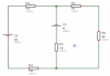
For the circuit shown in figure 3, calculate the voltage and current through resistor R2 and R3, using Kirchhoff's Laws. What is the power dissipated by R4.
I have attached a picture of a circuit, if anyone could help and explain that would be great
Im keen to learn more about electronic but struggling with this question.
For the circuit shown in figure 3, calculate the voltage and current through resistor R2 and R3, using Kirchhoff's Laws. What is the power dissipated by R4.
I have attached a picture of a circuit, if anyone could help and explain that would be great