James Williams
- Mar 4, 2016
- 2
- Joined
- Mar 4, 2016
- Messages
- 2
I'm a student who's building a kinetic phone charger for my project in engineering.
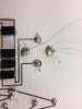
The problem is that when I test the kinetic device directly with the multimeter I get between 10 - 40 v AC. The second I solder the device to the PCB and test it at that point, I'm not even getting 1v AC. This is before any resistance can effect anything as I'm testing it at the same point as before, only connected to the PCB. The component I'm soldering it on to is a rectifier, so converting AC to DC but again I'm not testing it after its converted, I'm testing it before I am.
I have scrapped off the enamel on the copper wirer and soldered it. Still same problem. Then soldered wirers onto the copper and tested it and it works, but again when I solder it onto the PCB I get below 1v AC.
Another thing I tried was soldering it to a 50v max voltage, three pin connector and tested it before, getting again 10-40 volts. But the second I connect the other connecter, I have the same problem as with soldering it onto the PCB.
If anyone has any ideas or can see the stupid thing that I've done, please help.