Maker Pro
Maker Pro

input / output of op amp

Ledwardz

Dec 21, 2010
43
Joined
Dec 21, 2010
Messages
43
hey,

if im told that the non inverting op amp input is 4v
and the inverting input is 6sin (omega thingy) t
its also open loop i.e no Rf so i called gain A
owww and power is 10 n -10

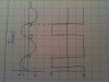
ok, it asks me to draw input and ouput of op-amp

input is easy enough but is the output

vo = A( V non inverting - V inverting ) ????

in which case i get A(4 - Vin)

so the output should look like input inverted and shifted by errrrr 4 to the left but 4???
the x axis of my graph is in radians. Also i have somewhere in my notes that the output is a square wave, is this right?

am i doing the complete wrong thing ????? any help much appreciated. Thanks.
 

Laplace

Apr 4, 2010
1,252
Joined
Apr 4, 2010
Messages
1,252
If instead of using an op amp, you substituted a comparator into the same circuit, what would the output look like? How is an open-loop op amp different from a comparator?
 

Ledwardz

Dec 21, 2010
43
Joined
Dec 21, 2010
Messages
43
If instead of using an op amp, you substituted a comparator into the same circuit, what would the output look like? How is an open-loop op amp different from a comparator?

a comparator has an output of 2 states so i presume when the 6sint goes above 4 it would go high to tell you that the input is positive? i read tht on a website tho? my notes say nothing at all about a comparator output.

errr op amp amplifies the difference between the two inputs of the op amp and comparator is used to find a difference between the inputs and give a high or low output i think. If the op amp is open circuit it has a large gain 10^5 or something which means it acts like a comparator explaining the square wave.

the only difference between them is maybe speed of change because of saturation??? which would create a square wave with slightly sloped sides but i don't think thats the answer u were after?
 

Laplace

Apr 4, 2010
1,252
Joined
Apr 4, 2010
Messages
1,252
It's just that you started out by writing an equation for the op amp working in its linear region, which is only valid when the input signal is a few microvolts on either side of 4 volts. For all other values of input voltage the op amp is driven into saturation. To think like an engineer, don't write that equation. Instead draw a sine wave representing the input signal, then draw a horizontal line over it at the 4 volt level. Where the line and the sine intersect, those are your switching points. What percent of the time is the output high, and what percent is it low?
 

Ledwardz

Dec 21, 2010
43
Joined
Dec 21, 2010
Messages
43
It's just that you started out by writing an equation for the op amp working in its linear region, which is only valid when the input signal is a few microvolts on either side of 4 volts. For all other values of input voltage the op amp is driven into saturation. To think like an engineer, don't write that equation. Instead draw a sine wave representing the input signal, then draw a horizontal line over it at the 4 volt level. Where the line and the sine intersect, those are your switching points. What percent of the time is the output high, and what percent is it low?

so it looks something like this?
 

Attachments

  • meh.jpg
    meh.jpg
    21.2 KB · Views: 465
Top