Maker Pro
Maker Pro

I'm Back- sort of

bertus

Moderator
Nov 8, 2019
3,330
Joined
Nov 8, 2019
Messages
3,330
Hello,

The 1N914 and 1N4148 are almost the same.
Here are two datasheets that will share info on both diodes.
As for the led, the forward voltage will depend on the color of the led.
Led_color_chart.png

Bertus
 

Attachments

  • 1N914_fair.pdf
    77.4 KB · Views: 0
  • 1N914_micro.pdf
    104.4 KB · Views: 0

SparkyCal

Mar 11, 2020
849
Joined
Mar 11, 2020
Messages
849
Thanks Bertus. So, if they are almost the same, the ear test may be best. I will probably go with the IN4148 on this particular circuit, but when I get to breadboarding, it will be interesting to experiment with all of them, including LEDs. Thanks for the chart!
 

Audioguru

Sep 24, 2016
3,656
Joined
Sep 24, 2016
Messages
3,656
The very high output level of the opamp without diodes will have loud and harsh distortion, but only if you reduce the input level feeding your power amplifier to prevent the power amplifier from clipping.
The much lower level with diodes will have softer distortion.
The 1N4148 and 1N914 diodes will sound the same. Leds will sound a little louder and a little different. Larger "rectifier" diodes are made for 50Hz or 60Hz electricity and might muffle audio distortion. Try all of the different types.

EDIT: You want a switch in series with the diodes not in parallel bypassing them.

Since I like hearing squeaky clean sounds I always avoid distortion.
 

SparkyCal

Mar 11, 2020
849
Joined
Mar 11, 2020
Messages
849
Here is a short clip[ as to what the circuit sounds like:

I used a Fender road worn Brad Paisley telecaster ( a nice guitar), through the aforementioned Roland Micro Cube guitar amp. I had the Roland set on the Clean setting, with very very little volume and no gain (on the actual Roland amp). Also, no effects were applied.
If I would have turned the volume on the cube to 9 o clock, I probably would have blew the roof off (the cubes pack quite a punch too).

https://drive.google.com/file/d/1mNolAGU5iFVfTP_4_bJq_1zg1_TBp_oo/view?usp=sharing

What do you think so far?
 

Audioguru

Sep 24, 2016
3,656
Joined
Sep 24, 2016
Messages
3,656
The guitar recording seems to have the high frequencies cut but sounds clear and clean.
I played a trombone in my high school band and travelled all over British Columbia winning band contests. Live, no amplifier or speakers.
 

SparkyCal

Mar 11, 2020
849
Joined
Mar 11, 2020
Messages
849
Leading to my next question. I am under the impression that the choice of filtering, by way of capacitors, impacts high pass and low pass frequencies. If that's true, I assume we can achieve more high frequencies by changing capacitor values? If so, through OHMs law, does that affect a complete reconsideration of all values in the circuit, including resistor values? I'm not saying. to do this now, but just wondering.

I think the advent of the electric guitar, changed a lot of things, some for the better and some for the worse. The big band sound died when rock started flourishing. I'm not sure that's a good thing. Interesting to hear Brian Seltzer, who manages to combine the big band sound with electric guitar. Or Robert Plant's The Honeydrippers.
 
Last edited:

Audioguru

Sep 24, 2016
3,656
Joined
Sep 24, 2016
Messages
3,656
To make high frequencies appear to be boosted, resistors and capacitors can reduce the level of all low frequencies.

Most guitar speakers are missing the high frequencies above 2kHz or 3khz produced by a tweeter.
High frequencies are boosted up to normal (by the inductance of the pickup resonating with the capacitance of the cable) if the amplifier has a high input resistance like here:
 

Attachments

  • guitar pickup freq resp load effects.png
    guitar pickup freq resp load effects.png
    176.7 KB · Views: 3

SparkyCal

Mar 11, 2020
849
Joined
Mar 11, 2020
Messages
849
More progress. I installed the diodes and the distortion sounds a lot better.

However, the only part of the circuit that does not seem to be working as intended is the 500K Gain pot that comes after the C31 100pF capacitor and before R46 (1K) resistor.

If you imagine the pots prongs facing you, I shorted the middle prong to the prong on the right

Then I wired it as follows:

Left prong to the OUT (Pin 6 on schematic, Pin 1 on my 4558d op amp)

Right/Middle prong to - In (Pin 2 on the schematic and Pin 2 on my 4558D op amp).

When I turn the pot, it seems to have no effect on the sound. Did I wire it wrongly?
 

SparkyCal

Mar 11, 2020
849
Joined
Mar 11, 2020
Messages
849
Here is the way I am suggesting you look at the pot.
 

Attachments

  • pot.jpg
    pot.jpg
    22.7 KB · Views: 2

SparkyCal

Mar 11, 2020
849
Joined
Mar 11, 2020
Messages
849
Further illustration
 

Attachments

  • Photo on 2021-05-31 at 5.06 PM.jpg
    Photo on 2021-05-31 at 5.06 PM.jpg
    107 KB · Views: 3

Audioguru

Sep 24, 2016
3,656
Joined
Sep 24, 2016
Messages
3,656
If you look at the knob and see the slider going around the resistive track clockwise and counter-clockwise you can see the resistance changing.
Clockwise and the gain and distortion from the diodes are high.
Counter-clockwise and the gain is 1 and no distortion because the diodes are shorted.
 

Attachments

  • gain control.png
    gain control.png
    175 KB · Views: 2

SparkyCal

Mar 11, 2020
849
Joined
Mar 11, 2020
Messages
849
Thanks AG. Is the change supposed to be really noticeable when you work the pot, or is it more nuanced?
 

SparkyCal

Mar 11, 2020
849
Joined
Mar 11, 2020
Messages
849
Hey guys:

I have attached a sound file with the sound of the guitar, now that the diodes are in play.

I used the same Roland cube amp, but this time I used a Fender Squier Telecaster guitar. This is not an expensive guitar. But I wanted to use a cheaper guitar to see what it sounds like.

The clip includes the following:

First I am playing a chord, using both the neck and treble pickup on the guitar (a blend of the two pickups)

Then, when you hear me play Blackdog (sloppily), I am using the treble pick up only.

Then I am playing Rocky Mountain Way and using the neck pick up only.

FYI- the neck pickup usually carries more bass tones. The treble pick is more high end. The combo of the tweo produces a blend.

https://drive.google.com/file/d/1Sf0SYwxcQELLHc3iCrPRt62BMAb0V8xT/view?usp=sharing

You may hear some noise, which is typical for when using pedals. To combat that, I usually use a noise gate pedal when playing on stage (but not for this clip).

Noise gate pedals, or noise gate plug ins are almost essential when using these types of effects, so the noise you may hear, is typical.
 

Audioguru

Sep 24, 2016
3,656
Joined
Sep 24, 2016
Messages
3,656
Distortion produces many high frequency harmonics. If the amplifier and speakers (missing tweeters) cannot produce high frequencies then the severe distortion produced by the diodes when the gain pot is at maximum resistance might not be noticeable.
Here are frequency response graphs of typical guitar speakers:
 

Attachments

  • guitar speaker.png
    guitar speaker.png
    151.4 KB · Views: 0

SparkyCal

Mar 11, 2020
849
Joined
Mar 11, 2020
Messages
849
Yes, I do. This is great progress ( for me anyway), and for you guys for being patient teachers :)

I just finished installing C3 and the 270R resistor, Before I install the 10K Tone pot, I have the following important question:

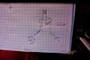
I have uploaded a graphic that you will need to refer to, to know what I am talking about.

On the graphic, you will see that I drew little dots in pencil, and beside those dots to their left, I numbered them 1. 2. 3. 4. and 5.

My question is I. reaction to the Gain pot, which is shown at number 1 ( Although I already installed this pot correctly, I need to know the answer to this question, as it will affect the way I wire things(

Ordinarily, I would solder point 1 to point 2

But (and here is the important part of my question), would it matter to the installation of the Gain pot, if I soldered point 1 to point 5?

In other words, is the sequence of the soldering important (ie: 1 goes to 2 goes to 3 goes to 4. goes to 5

OR

Because the Gain pot and C31 and D1 and D2 all share the same stream (as shown in the line that connects points 1, 2 ,3,4, and 5), does it matter if I am out of sequence and wire point 1 directly to point 5?

thank-you
 

Attachments

  • IMG_5096.jpg
    IMG_5096.jpg
    216.3 KB · Views: 2

SparkyCal

Mar 11, 2020
849
Joined
Mar 11, 2020
Messages
849
Also, the circuit calls for 10K tone pot. I only have 5 Ks or 20Ks. any advice?
 

Audioguru

Sep 24, 2016
3,656
Joined
Sep 24, 2016
Messages
3,656
Points 1, 2, 3, 4 and 5 should all be connected very close together. If they are miles apart then their wires would be antennas that pickup mains hum and all kinds of other interference.

The 10k tone control feeds C29 that is 22nF. Then when it is used at maximum resistance, 706Hz is reduced -3dB and higher frequencies are reduced -6db (half the voltage) per octave.
Use a 20k tone control and a 10nF capacitor.
 

SparkyCal

Mar 11, 2020
849
Joined
Mar 11, 2020
Messages
849
Thanks AG. In terms of my question about the sequence of the wiring, I'd like to take it out of the context of building a stompbox, for now ( I understand what you are saying about wires acting as antennas if far apart).

But what I am really trying to understand, is whether not connecting the wires sequentially, and connecting point 1 to point 5 directly, thereby coming before the connection to points 4, 3 and 2, would be a departure from what is called for in the circuit. In other words, would it screw things up if I did not follow the sequential wiring as described in the diagram?
 

Audioguru

Sep 24, 2016
3,656
Joined
Sep 24, 2016
Messages
3,656
The sequence of connecting the points 1 to 5 does not matter since they all connect to the same place in the circuit.
 
Top