Maker Pro
Maker Pro

Identifying parts of the FM kit

*Neon23

Mar 19, 2018
4
Joined
Mar 19, 2018
Messages
4
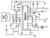
I would like to identify the parts of this FM radio schematic whether the caps, inductors or resistors comprises the RF amp, mixer, local oscillator, IF amp, FM demodulator and Automatic Frequency Control.


I have been searching for the specification sheet of the CXA2001 IC and unfortunately there is no existing file in the internet nor does the package i bought include it and I'm not so sure about the equivalent IC of CXA2001.

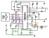
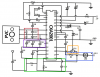
So here is the progress I have now
upload_2018-6-4_20-0-12.png

upload_2018-6-4_19-49-30.png

RED - LC TANK circuit
BLUE - Quadrature Detector
YELLOW - Crystal Oscillator
I assume the mixer is at the pins 12-15 and 16-19.
 

Attachments

  • upload_2018-6-4_19-38-24.png
    upload_2018-6-4_19-38-24.png
    259.8 KB · Views: 110
  • upload_2018-6-4_19-40-21.png
    upload_2018-6-4_19-40-21.png
    257.6 KB · Views: 111
  • upload_2018-6-4_19-59-43.png
    upload_2018-6-4_19-59-43.png
    256.5 KB · Views: 99

Audioguru

Sep 24, 2016
3,656
Joined
Sep 24, 2016
Messages
3,656
I think it is an old Sony IC with no datasheet available anymore. Use a more modern IC instead.
Its C11 might be a 10.7MHz crystal filter.
 

73's de Edd

Aug 21, 2015
3,622
Joined
Aug 21, 2015
Messages
3,622
Sir *Neon23 . . . . .

The CXA prefix is usually associated with Sony IC's.
And now I give you this utilization of a CXA1019 just for comparison.
You can see that they seem to fall in pin by pin.
Take particular note of the first few pages where they break down the pin by pin internal circuitry contents.

On your drawing that symbol that they were using for C11 . . . . . sort of threw me for a loop until I caught its number.
Those then immediately relate to a 10.7 Mhz ceramic IF filter.

The now supplied diagram also routes pin 28 to the speaker, while yours tells you nothing. (/P) phone ?

You do see that the 1019 is spec'd at 6VDC power,while yours is using 12VDC .
At any rate if you read all of the info supplied below you should be supplied well enough by its info to see if all relates to your unit also.

Looks like most of the unused pins are related to making the unit work as an AM receiver also.

http://www.electronicecircuits.com/electronic-circuits/cxa1019-fm-radio-circuit-diagram

Sony Data Sheet for a 1019 . . . . .

http://data.datasheetlib.com/pdf1/95/76/957608/cxa1019m_b99408fd23.pdf?take=binary


73's de Edd
.....
 
Top